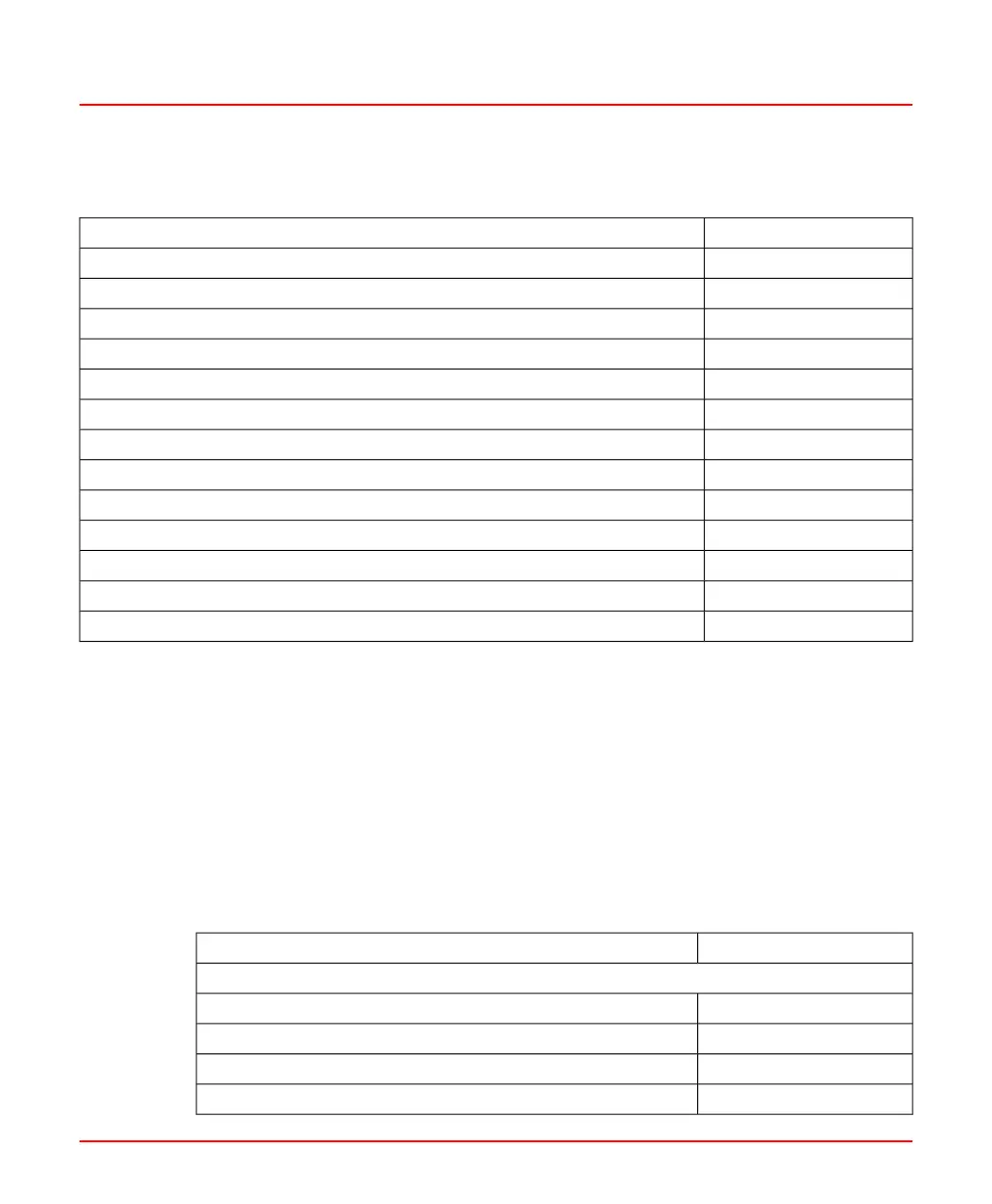
Table 15.4: Channel Configuration Parameter Registers (MODBUS)
(Continued)
Register AddressesScanner Configuration Parameters
4011Function Set Switch (Off, through Serial Line, and through Digital Inputs)
4012Enable High Limit (NO/YES)
4013Enable AC Amplitude (NO/YES)
4014-4017Unit ID
4018-4021Elevation ID
4022-4025Burner ID
4026-2029Function-set ID A
4030-4033Function-set ID B
4034AO Output mode
4035AO Output source (Intensity, Frequency, AC-Amplitude, Quality.CI)
4036-4056Spares
4056-4059Function-set ID C
4060-4063Function-set ID D
These values are read using MODBUS function code 3 and written to using MODBUS
function code 6 or 16.
The parameters require 64 MODBUS registers for the scanner configuration (including
spare registers provided for future expansion), and 40 registers for each of the four
function-sets (including spare registers). This is a total of 230 registers per scanner. This
means that two MODBUS requests are required to access all the parameters for one
SF910i scanner.
The user must update an entire Tuning Function-Set in one MODBUS request to ensure
that all the parameters are consistent and that all are accepted or all are rejected.
Table 15.5: Tuning Function-Set Parameter Registers (MODBUS)
Register AddressesTuning Function-Set Parameters
Function-set A
4070Intensity Trip Point Pull-In (IP)
4071Intensity Trip Point Drop-Out (ID)
4072Intensity Trip Point High (IH)
4073Intensity Normalization (IN)
8VZZ005286 B 103
15 Serial Interfaces
15.2 MODBUS Protocol