41
34ZBTS_30-1200A rev.A / 1SCC303043M0201
1
ATS is swithed OFF, the racking out is started;
Bypass is connected to the same source
as ATS was earlier and operates the load
HMI of ATS:
Page “Switch Overview”
HMI of Bypass:
Page “Bypass System Overview”
(the last page in “Switch Overview” -navigation)
ATS has reached the Test location, Bypass supplies
the load. The next step; the racking out is started
in ATS (to Isolated location), the display will be same
as in the upper picture (ATS Status: all in gray)
Switch in O position
ATS Test
Load Current
0.0 A
05:14
G
TruONE ATS
Switch Overview
S1 p Ok Ok S2
ATS is reached the Test location, control power
is available. All electrical operations are still
allowed to ATS
05:10
TruONE ATS
Bypass System Overview
The racking out is started in ATS (to TEST location);
Bypass supplies the load
Test
ATS is reached the Isolated location, HMI of ATS
lost the power
The racking out is completed in ATS; Bypass
supplies the load, HMI of Bypass is working as
normal and shows the status of both switches
Iso-
lated
05:21
TruONE ATS
Bypass System Overview
G
Bypass Status
Connected
Test
Isolated
ATS Status
Connected
Test
Isolated
05:17
TruONE ATS
Bypass System Overview
G
Bypass Status
Connected
Test
Isolated
ATS Status
Connected
Test
Isolated
ATS Status
Connected
Test
Isolated
Bypass Status
Connected
Test
Isolated
Switch in O position
- - -
Load Current
.... A
05:09
G
Switch Overview
S1 p Ok Ok S2
Racking Enabled
TruONE ATS
G
—
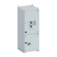
Fig. 3.29 Status of the switches on the HMIs of both switches while racking out the ATS

 Loading...