www.accuenergy.com
V: 1.0 Revised: Jan. 2018
10
AcuDC 240 Series
DC Energy & Power meters
2. Tighten the installation screws.
Note: Install I/O Module carefully to avoid damage; under no circumstances should any
installation be done with the meter powered on. Failure to do so may result in injury or
death.
2.2.3 Mounting Meter Onto Switchboard Panel
Appearance and Dimensions
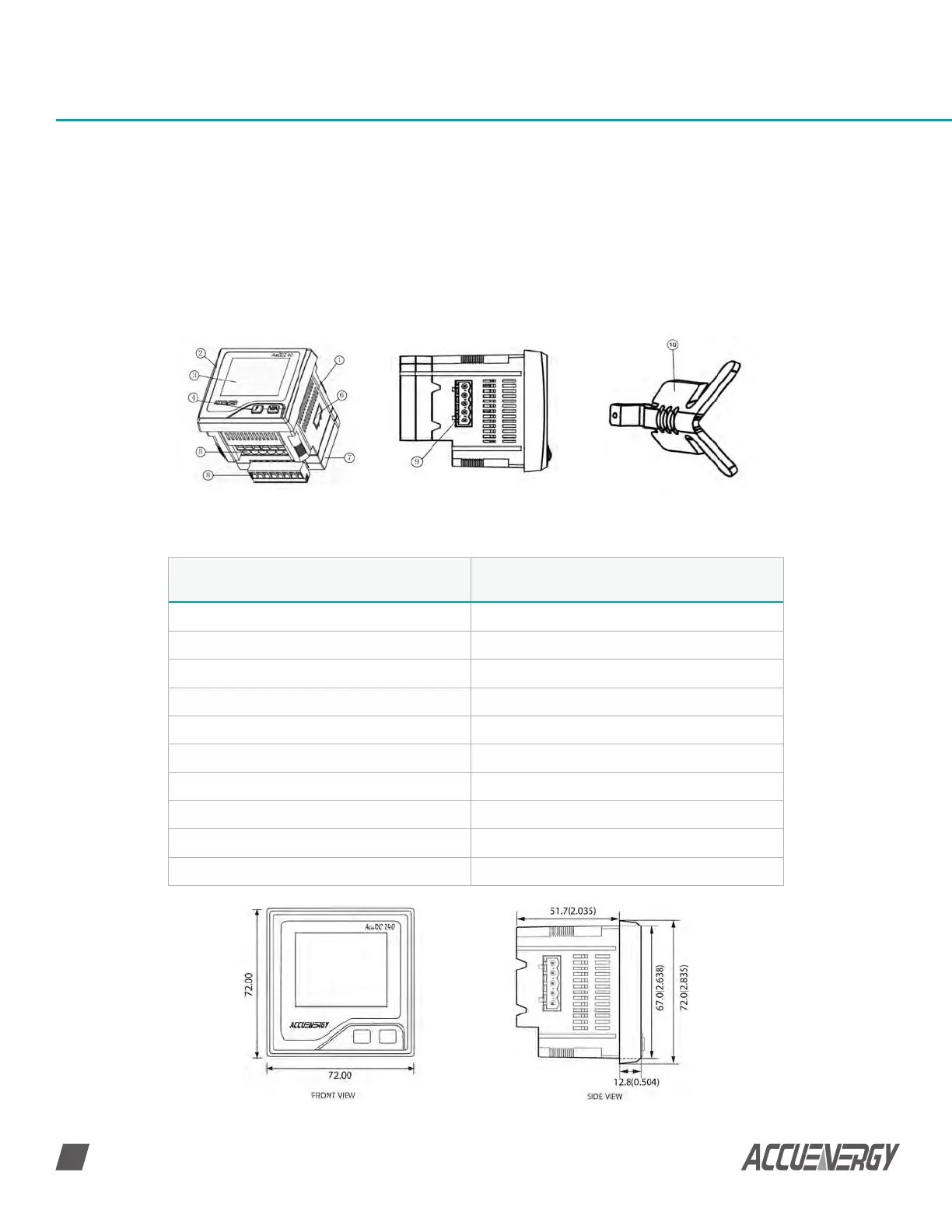
Fig 2-3 AcuDC 240 Appearance
Table 2-1 Part Name of AcuDC 240
Fig 2-4 AcuDC 240 Dimensions
Part Description
1. Casing High intensity fire resistant engineering plastics
2. Front Casing Visible portion after mounting onto a panel
3. Display Large LCD display
4. Key Two keys are used to select display and set
5. Voltage and Current Input Terminals Used for voltage and current input
6. Communication Terminals Communication output
7. I/O Module Optional I/O module
8. I/O Terminal Optional I/O terminals, including 2DI, 2AO/2RO
9. Power Supply Terminal Power supply terminal
10. Installation Clips Used for securing the meter to the panel
 Loading...


