www.accuenergy.com
V: 1.0 Revised: Jan. 2018
61
Appendix
Why is my AcuDC 243 measuring the wrong current with the shunt I am using?
• The shunt should be installed on the negative side of the load.
• Ensure that the AcuDC 243 is wired correctly to the shunt so that it can be read
accurately.
• The positive output from the shunt should be connected to the AcuDC 243 ‘I+’
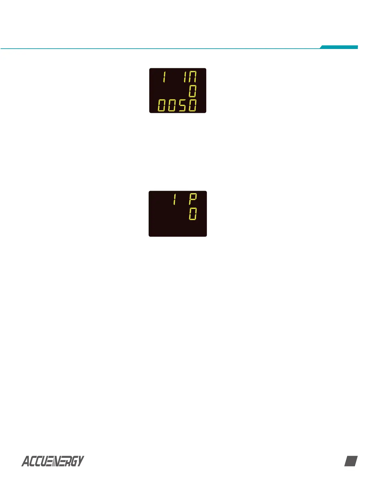
•• Press ‘V/A’ to go to the next screen. This will be the ‘I P’ screen. This setting
corresponds to the output range of the Hall Effect Sensor.
•• Press ‘F’ to change this setting and to select required output.
•• Press ‘V/A’ to confirm this setting; the cursor will stop flashing at this point
SET
NOTE: The default setting is ‘0’ for 4-20mA/0-±5V. The other mode is ‘1’ for
4-12-20mA/0-±4V.
SET
terminal.
• The negative output from the shunt should be connected to the ‘AcuDC 243
‘I-‘terminal.
• If the voltage is also being measured ensure that the positive DC source is
connected to the AcuDC 243 ‘V+’ terminal whiles the AcuDC 243 ‘V-‘ terminal should
be connected to the ‘I-‘ terminal on the AcuDC 243.
• Ensure that the shunt being used outputs a signal in the range of 50-100mV to work
with the meters current input.
• Check that the settings in the meter are configured to read accurately from the shunt.
• Press ‘F’ and ‘V/A’ simultaneously whiles on the meter data mode to get to the
settings mode.
 Loading...


