EVO 150 Controller
46
Appendix 8 / Inhibit Input
The INHIBIT input allows the actuator to be turned off (inhibited) by a customer-supplied control
signal.
There are four customer-selectable INHIBIT operating modes. These modes are controlled by
parameter 19. Refer to page 21 for more information about setting controller parameters.
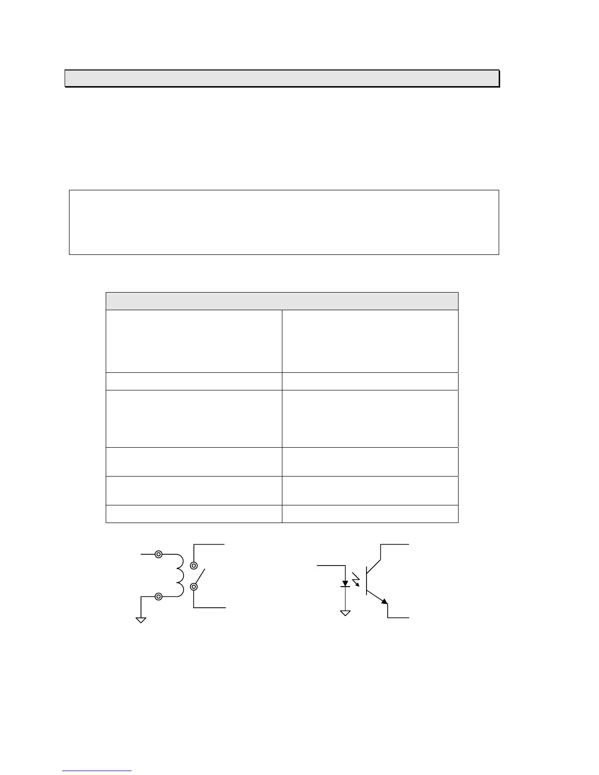
The INHIBIT input requires an isolated contact closure. To activate or deactivate the INHIBIT
input, close (short) or open the connection between J3 terminals 5 and 6 (refer to the diagram
below).
Note: The INHIBIT input will override all PLC I/O inputs. To allow the PLC I/O inputs to operate
properly, the INHIBIT input must be inactive.
Note: The INHIBIT input is not opto-isolated. If your application requires an opto-isolated
INHIBIT input, then set parameter 72 to 1. Refer to page 21 for more information about setting
controller parameters.
Electrical Specifications:
Non-isolated contact-closure input
Description This input must be connected to an
isolated contact or a sink-connected
(NPN) opto-coupled transistor output.
It must not be connected to anything
else.
Connector J3
Terminals 5 – Signal input (connect to collector
of customer-supplied opto-coupler)
6 – Signal GND (connect to emitter of
customer-supplied opto-coupler)
Input voltage Internally pulled to +5 VDC through a
5 K-ohm resistor
Input current 1 mA to turn on, 0.27 mA or less to
turn off
Isolation None, provided by customer
INHIBIT J3-5 J3-5
Signal INHIBIT
Signal
J3-6
J3-6
Relay Control Solid State Control