Home
Acer
Projector
H6500
Page 47
Acer H6500 - Page 47
111 pages
Manual
Save Page as PDF
To Next Page
To Next Page
To Previous Page
To Previous Page
Loading...
Condential
2-27
H6500
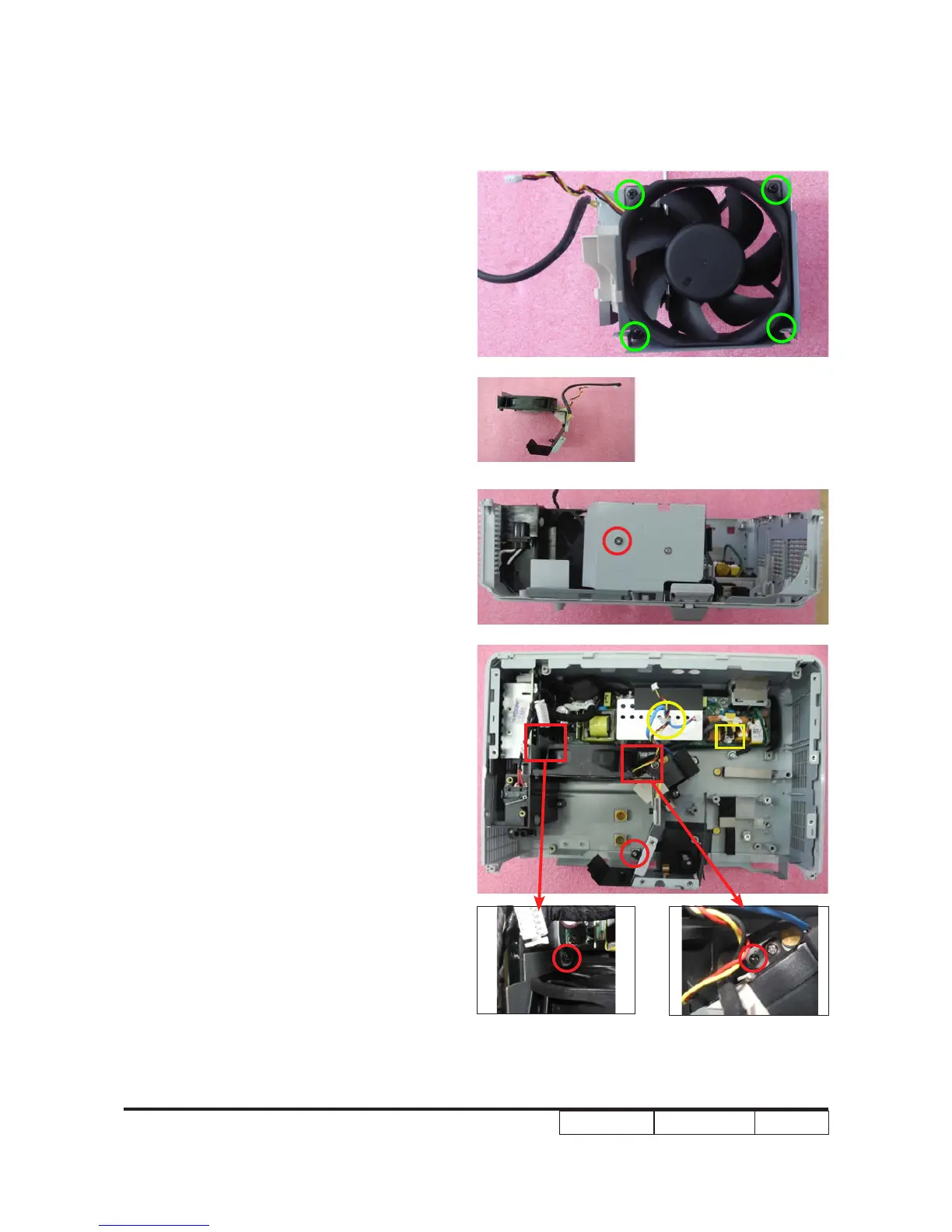
5. Screw 4 screws (as green circle) to
assemble System fan and Fan shielding.
6. Screw 4 screws (as red circle) to
assemble System Fan Module.
7. Use a cable tie to x Blower and System
fan cable (as yellow circle).
46
48
Table of Contents
Main Page
Default Chapter
1
Service Manual
1
Table of Contents
3
Chapter 1 Introduction
6
Highlight
6
Compatible Mode
9
Product Overview
12
Rear Side
13
Control Panel
14
Getting Started
18
Chapter 2 Disassembly Process & Assembly Process
21
Equipment Needed & Product Overview
21
Disassemble Lamp Module
22
Disassemble Top Cover Module
23
Disassemble Keypad Board and Zoom Ring
24
Disassemble Main Board Module
25
Disassemble Front Cover Module
28
Disassemble Color Wheel Module
29
Disassemble Engine Module
30
Disassemble DMD Chip and DMD Board
30
Disassemble System Fan Module and the Blower Module
32
Disassemble LVPS Module
35
Disassemble Lamp Driver Module and Interrupt Switch
36
Disassemble Bottom Shielding and IO Cover Module
38
Disassemble Elevator Foot Rubber
39
Rod Adjustment
40
Re-Write System and Lamp Usage Hour
41
Assemble Bottom Shielding and IO Cover Module
42
Assemble Elevator Foot Rubber
42
Assemble Lamp Driver Module and Interrupt Switch
43
Assemble LVPS Module
45
Assemble System Fan Module and the Blower Module
46
Assemble DMD Chip and DMD Board
48
Assemble Engine Module
49
Assemble Color Wheel Module
49
Assemble Front Cover Module
51
Assemble Main Board Module
51
Assemble Keypad Board and Zoom Ring
53
Assemble Top Cover Module
54
Assemble Lamp Module
55
Chapter 3 Troubleshooting
56
LED Lighting Message
56
Main Procedure
57
Chapter 4 Function Test & Alignment Procedure
62
Test Equipment Needed
62
Service Mode
62
OSD Reset
62
Test Condition
63
Test Inspection Procedure
64
PC Mode
65
Calibration
68
Video Performance
70
Optical Performance Measure
71
Others
73
Chapter 5 Firmware Upgrade
74
Equipment Needed
74
Get into Firmware Download Mode
75
Install USB Driver
75
Firmware Upgrade Procedure
77
Waveform Download
79
Restore Fan Speed
79
Chapter 6 EDID Upgrade
80
EDID Introduction
80
Equipment Needed
81
Enter EDID Firmware Mode
82
Setup Procedure (VGA & HDMI 1)
82
EDID Key-In Procedure (VGA & HDMI 1)
83
Setup Procedure ( HDMI 2)
86
Un-Lock SNID and Default Language Reset
89
Fru List
106
Appendix A
110
Appendix B
110
Serial Number System Definition
110
PCBA Code Definition
111
Related product manuals
Acer H6546Ki
95 pages
Acer H6545BD
99 pages
Acer H6531BD
67 pages
Acer H6510BD
13 pages
Acer H6517ST
71 pages
Acer H6540BD
99 pages
Acer H6536BD
67 pages
Acer H6555AKi
95 pages
Acer H6518STi
95 pages
Acer H6510BD Series
69 pages
Acer H6531BDK Series
68 pages
Acer H6555ABDKi Series
59 pages