EasyManua.ls Logo

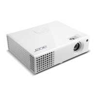
Acer H6500 - User Manual

Acer H6500
111 pages
To Next Page IconTo Next Page
Loading...
SERVICE MANUAL
Prepared: Checked: Approved:
Date Revise Version Description
2011.09.14 V1.0 Initial Issue
Copyright September, 2011 All Rights Reserved
H6500
Alex

Table of Contents

Questions and Answers:

Acer H6500 Specifications

General IconGeneral
Number of colors1.073 billion colors
Projection distance1.5 - 10 m
Horizontal scan range0 - 100 kHz
Projection technologyDLP
Contrast ratio (typical)10000:1
Screen size compatibility0 - 300 \
Projector native resolution1080p (1920x1080)
Keystone correction, vertical-15 - 15 °
Projector brightness (economic mode)1600 ANSI lumens
Aspect ratio4:3, 16:9
RS-232 ports-
Connectivity technologyWired
Digital zoom8 x
Optical zoom1.2 x
Focal length range- mm
Aperture range (F-F)2.55 - 2.85
Lamp typeOSRAM
Lamp power240 W
Lamps quantity1 lamp(s)
Light source typeLamp
Service life of light source5000 h
Service life of light source (economic mode)3500 h
3DNo
Full HDYes
Supported video modes1080p
Analog signal format systemNTSC, PAL, SECAM
Supported graphics resolutions1920 x 1080 (HD 1080)
USB 2.0 ports quantityUSB 2.0 ports have a data transmission speed of 480 Mbps, and are backwards compatible with USB 1.1 ports. You can connect all kinds of peripheral devices to them.
Noise level- dB
PlacementCeiling
Product typeStandard throw projector
Product colorWhite
Market positioningHome cinema
Power sourceAC
AC input voltage110 - 220 V
Power consumption (standby)- W
Weight and Dimensions IconWeight and Dimensions
Weight2540 g

Summary

Getting Started

Connecting the Projector

Illustrates how to connect various devices like DVD players and PCs to the projector.

Chapter 2 Disassembly & Assembly Process

2-2 Disassemble Lamp module

Step-by-step instructions for removing the lamp module from the projector.

2-3 Disassemble Top cover module

Instructions for safely removing the projector's top cover module.

2-4 Disassemble Keypad board and Zoom ring

Guide for disassembling the keypad board and zoom ring components.

2-5 Disassemble Main board module

Detailed steps for removing the main board module and its associated shielding.

2-6 Disassemble Front cover module

Instructions for removing the front cover module and IR sensor board.

2-7 Disassemble Color wheel module

Steps for removing the color wheel module and associated sensors.

2-8 Disassemble Engine module

Guide for removing the engine module, including spacers and focus ring.

2-10 Disassemble System fan module and the Blower module

Steps for removing the system fan and blower modules.

2-11 Disassemble LVPS module

Instructions for removing the LVPS module, including connectors and brackets.

2-12 Disassemble Lamp driver module and Interrupt switch

Guide for disassembling the lamp driver module and interrupt switch.

2-13 Disassemble Bottom shielding and IO cover module

Steps for removing the bottom shielding and IO cover module.

2-14 Disassemble Elevator foot rubber

Instructions for removing the elevator foot rubber from the projector base.

2-16 Re-write System and Lamp usage hour

Instructions for accessing service mode to re-write system and lamp usage hours.

2-19 Assemble Lamp driver module and Interrupt switch

Guide for reassembling the lamp driver module and interrupt switch.

2-20 Assemble LVPS module

Instructions for reassembling the LVPS module and associated components.

2-21 Assemble System fan module and the Blower module

Steps for reassembling the system fan and blower modules.

2-22 Assemble DMD chip and DMD board

Guide for reassembling the DMD chip and its board.

2-23 Assemble Engine module

Instructions for reassembling the engine module and its parts.

2-25 Assemble Front cover module

Guide for reassembling the front cover module and IR sensor board.

2-26 Assemble Main board module

Detailed steps for reassembling the main board module and its connections.

2-27 Assemble Keypad board module and Zoom ring

Instructions for reassembling the keypad board and zoom ring components.

2-28 Assemble Top cover module

Steps for reassembling the projector's top cover module.

2-29 Assemble Lamp module

Instructions for reassembling the lamp module and its cover.

2-9 Disassemble DMD chip and DMD board

Instructions for disassembling the DMD chip and its board.

2-24 Assemble Color wheel module

Steps for reassembling the color wheel module and associated sensors.

Chapter 3 Troubleshooting

3-1 LED Lighting Message

Explains LED status indicators for various messages and error conditions.

3-2 Main Procedure

Provides a troubleshooting guide for common issues like no power or auto shutdown.

No Image

Troubleshooting steps for scenarios where the projector displays no image.

Color Abnormal

Troubleshooting steps for abnormal color reproduction or color temperature issues.

Universal Password Failure

Troubleshooting steps for universal password failures and SNID confirmation.

Forgetting Password (administrator Password)

Procedure to recover the administrator password using the SNID.

FW Upgrade Failed

Steps to diagnose and resolve firmware upgrade failures.

Line Bar;Line Defect

Troubleshooting steps for image defects such as line bars or defects.

Dead Pixel;Dust (Out of spec.)

Troubleshooting for dead pixels or dust affecting image quality.

Image Flicker

Steps to resolve issues causing the projected image to flicker.

Garbage Image

Steps to resolve issues causing distorted or garbage images on the screen.

Remote Controller;Control Panel Failed

Troubleshooting for failures in the remote control or the projector's control panel.

Chapter 4 Function Test & Alignment Procedure

Chapter 5 Firmware Upgrade

5-4 Firmware upgrade procedure

Detailed steps for performing the firmware upgrade process.

Chapter 6 EDID Upgrade

6-5 EDID Key-In Procedure (VGA &HDMI 1 )

Procedure for keying in EDID data for VGA and HDMI 1 connections.

6-7 EDID Key-In Procedure ( HDMI2 )

Procedure for keying in EDID data for HDMI 2 connection.

6-8 Un-lock SNID and Default Language Reset

Procedure to unlock SNID and reset default language settings.

Appendix A (Exploded Image)

FRU list

Related product manuals