Page 6
Connect and Terminate the Bus
The “Bus Connectors” are all wired in parallel. Use Cat 5, 4 twisted pair wire.
1= (Nominal Ground or Common of System) The Green Pair wired together
2= (Data Wire “A”) The Orange wire of the Orange White Pair
3= (Data Wire “B”) The White wire of the Orange White Pair
4= (+12 Volt dc to power switches) The Blue White Pair wired together.
Note: In earlier manuals a different color code was used. If adding to an older
system make sure your color code is exactly the same as the old system.
On panel control cards there are two connectors. These are in parallel. It is a
good idea to have one cable come in and one out so that the bus can be “op-
ened” for trouble shooting.
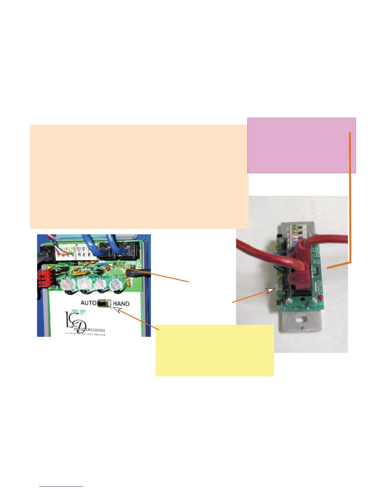
Blue End of bus
Terminator Installed
Location of Terminator pins
on the back of a switch
Make sure the numbered
switches are connected at
the correct locations as per
the switch schedules or the
programming will be incor-
rect.
Back View of a Digital Switch
Showing the Bus Connector
Hook up.
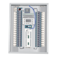
Close Up of a Relay Panel control card
showing the four Bus Connectors. Two
RJ 45s and two “1-2-3-4 connectors.”
Cat 5 Cable
Note the HAND/AUTO switch. Use
this to keep the relays ON w hile
testing the system. All LEDs on the
control cards and switches will
still indicate even with the relays
locked ON.