25
C. PROGRAMMING FLOWCHARTS
The following section of this manual explains the programming of the Phase 7 dual microprocessor controller
(DMC) computer program locations (system parameters) through the use of flowcharts. A flowchart is a diagram
of the programming process.
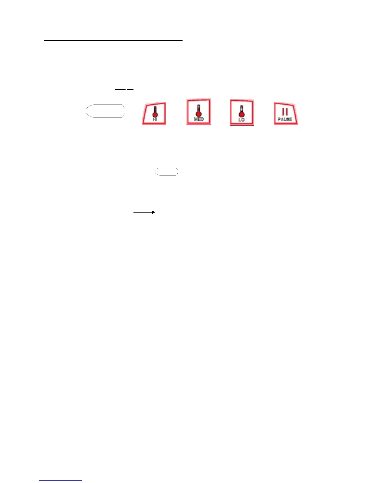
Five (5) different symbols will be used in these flowcharts:
display symbol
HI MED LO PAUSE
Each display symbol will represent a readout on the Phase 7 DMC (computer) liquid crystal display (L.C.D.), and
each key symbol will represent a key that is pressed. For example:
1. If the flowchart shows the symbol , the Phase 7 DMC (computer) L.C.D. display will read the
same.
2. If the flowchart shows a key symbol, you will press that specific key on the keyboard (touch pad) label.
3. The flowchart arrows (i.e., ) represent the program path.
On the sides of these flowcharts are explanations of the flowchart procedure and, in some cases, the
programming limits or options.
Listed on the next page is an index of the flowcharts to follow.
Ready
Ready