Home
ADCMT
Measuring Instruments
8230E
ADCMT 8230E User Manual
5
of 1
of 1 rating
114 pages
Give review
Manual
Specs
To Next Page
To Next Page
To Previous Page
To Previous Page
Loading...
8230E Optical Power Meter
Operation Manual
2. P
ANEL AND
FUNCTION DES
CRIP
TION
2-1
2.
PANEL AND FU
NCT
ION DESCRI
PTION
2.1
Front Side
2.1.1
Function Description
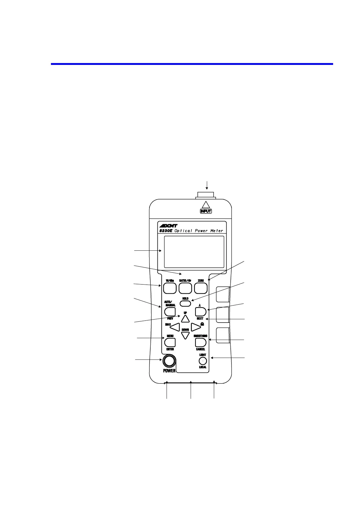
Figure 2-1
Front V
iew
1.
Display
Displays the measur
emen
t val
ue an
d othe
r in
form
ati
on.
2.
POWER
T
urns
on or of
f the power
.
1
2
3
4
5
6
7
8
9
10
11
12
13
14
15
1
6
17
32
34
Table of Contents
Table of Contents
11
Introduction
19
Product Outline
19
Standard Accessory
19
Standard Accessories
19
Accessories
20
Connectable Sensors
21
Old and New Model Numbers of Optical Sensors
22
Connection Diagram for Sensors
23
Optical Power Meter Software Revisions and Applicable Optical Sensors
24
List of Software Revisions Required for Optical Sensor Operations
24
Options and Accessories
25
Option to Use Old-Type Sensors (OPT8230E+70)
25
Sensor Option
25
Operating Environment
26
Battery
26
How to Remove and Replace Batteries
27
Battery Cover
27
Battery Alignment
27
Precautions When Using this Instrument
28
1.10 Checking Operations
28
1.11 Cleaning
29
Cleaning the 8230E
29
Cleaning the Incident Surface of the Sensor
29
1.12 How to Store and Transport the Instrument
29
Storage
29
Transportation
29
1.13 Warm-Up
30
1.14 Calibration
30
1.15 Replacing Parts with Limited Life
30
1.16 Product Disposal and Recycle
31
Panel and Function Description
33
Front Side
33
Function Description
33
Front View
33
2.1.2 Display Description
37
Battery Indicator
37
Rear Side
38
Rear View
38
Upper Side
39
Bottom Side
39
Top View
39
Bottom View
39
How to Perform Measurements
41
Menu Map
41
Menu Description
42
Measurement Procedure
43
Connecting the Sensor
43
Setting the Wavelength
43
Zero Cancel
43
Setting the Range
43
Reading the Display
43
Backing up and Initializing the Setting Parameter
44
Backing up the Setting Parameter
44
Initial Values of the Parameters and Backup
44
3.4.2 How to Initialize
45
Outline of the Parameter Backup
45
Wavelength Preset
46
Setting the Preset Wavelength
46
Setting the Preset Wavelength
47
Calling the Preset Wavelength
48
Remote Controlling Via Usb
49
Outline
49
USB Specifications
49
Setting up the USB Port
49
Driver for Control
49
Connecting to a Personal Computer
50
Setting the MYID
50
Response to the *IDN? Command
50
Measurement Data Output Format
52
Status Register
56
Status Register Structure
56
Status Byte Register
57
Device Event Status Register
58
Standard Event Status Register
59
Error Register
60
How to Set the Remote Command
61
Linking a Header to an Argument
61
Command Separator
62
Command Terminator
62
Executing Commands
62
Remote Control Command List
63
Initial Value
63
Availability
63
Remote Control Commands
63
4.7 Sample Programs
70
Program Example 1
70
Measurement Image
70
Display
71
Program Example 2
72
Measurement Image
72
Technical Notes
75
Principle of Measurement
75
Block Diagram
76
Optical Power Calibration and Wavelength Sensitivity Correction
77
Wavelength Sensitivity Characteristics and Power Calibration of the Sensor
77
Analog out
78
Relationship between the Current Range and the Output Voltage at Analog Output
78
Performance Test
79
Performance Test for the 8230E
79
Cable and Adapters Required for Performance Test
79
Instruments Required for Current Measurement Calibration and Performance
79
6.1.1 How to Connect Instruments
80
How to Test the Performance
80
Connection Diagram for Performance Test
80
Current Range Accuracy Specifications
81
Measuring Instruments and Other Equipment Required to Check the Performance of the Optical Sensor
83
Equipment Required for Evaluating Optical Sensors
83
How to Connect the Instrument
84
Test Point and Judgment Criteria
84
Connection Diagram for the Optical Sensor Performance Test
84
Judgment Criteria for the Optical Sensor
84
Test Procedure
85
Calibration
87
Measuring Instrument, Cable, and Other Instruments Required for Calibration
87
Cables, Adapters, and Others Required for Calibration
87
Precautions
88
How to Connect the Instrument
89
Connection Diagram for the IV Offset Calibration
89
Connection Diagram for the Current Measurement Calibration
89
Current Measurement Calibration Point and Its Allowable Range
90
Current Measurement Calibration
90
Calibration Point and Its Allowable Range
90
Calibration Operation
91
Calibration Flow
91
Current Measurement Calibration Flow
93
Calibration Procedure
94
Offset Calibration
94
Current Measurement Calibration
94
Specifications
97
8230E Specifications
97
Instrument Specifications
97
General Specifications
99
Standard Accessories
99
Optical Sensor Specifications
100
Sensor Specifications (Sold Separately)
100
Wavelength Sensitivity Correction Option and Additional Calibration Wavelength Option
102
Appendix
103
Trouble Shooting (before Asking for Repair
103
Problem and Solution
103
A.2 Error Messages
104
Error Message
104
Causes of the Generated Calibration Errors
105
8230E Dimensional Outline Drawing
107
5
Based on 1 rating
Ask a question
Give review
Questions and Answers:
Need help?
Do you have a question about the ADCMT 8230E and is the answer not in the manual?
Ask a question
ADCMT 8230E Specifications
General
Brand
ADCMT
Model
8230E
Category
Measuring Instruments
Language
English
Related product manuals
ADCMT 8230
120 pages
ADCMT 823B Series
120 pages
ADCMT 12704A
28 pages
ADCMT 6243
296 pages
ADCMT 6244
296 pages
ADCMT 6166
274 pages