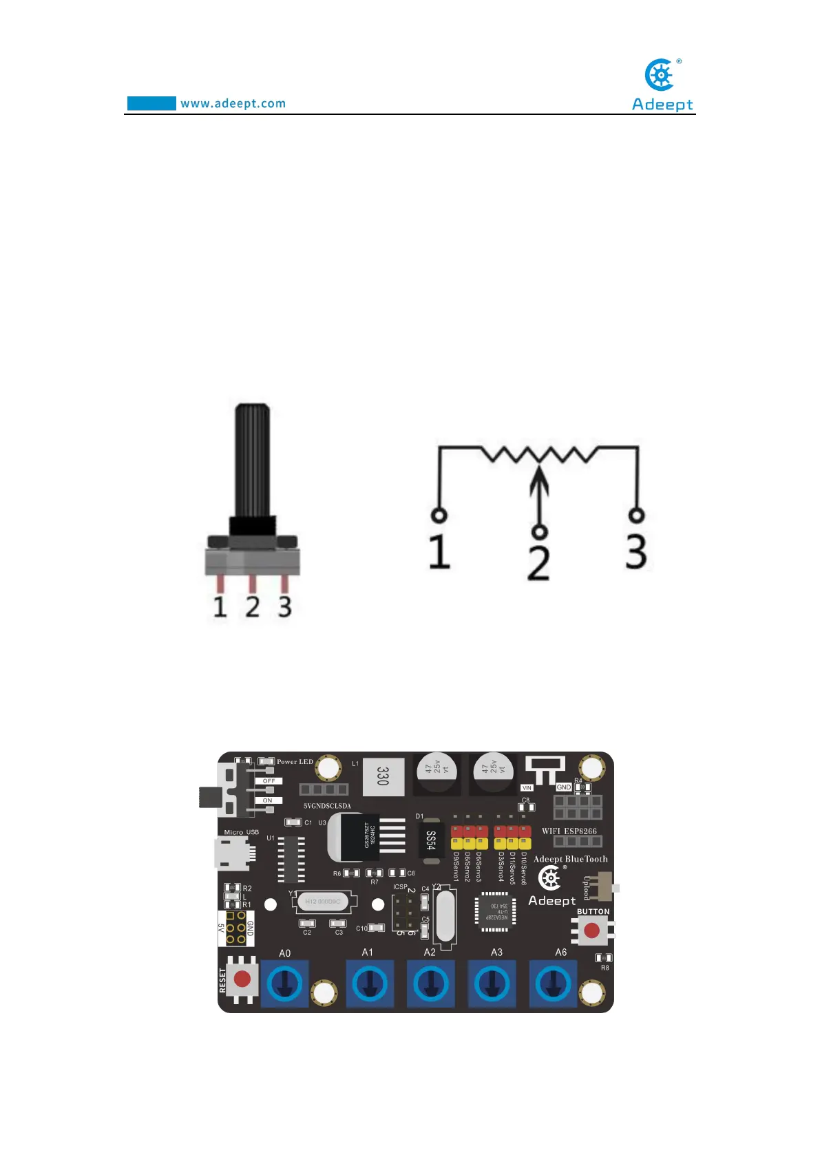
fixed contact. Potentiometer can be used to adjust the voltage and current.
Our course uses a rotary potentiometer. Its structure is as shown in the figure
below. By rotating the knob, the position of pin 2 is changed, thereby changing the
resistance value from pin 2 to both ends. In the experiment. Connect pin 1 and pin 3
to the GND and 5V of the development board respectively. And then read the voltage
divided by the pin 2 of the potentiometer through the analog input pin A0. The range
is between 0V and 5V. The analog input function of Arduino has 10-bit precision, that
is, it can convert the voltage signal of 0 to 5V into an integer form of 0 to 1024.
1.3 Wiring diagram (Circuit diagram)
Figure as below
: