Introduction 19
MXE-5400
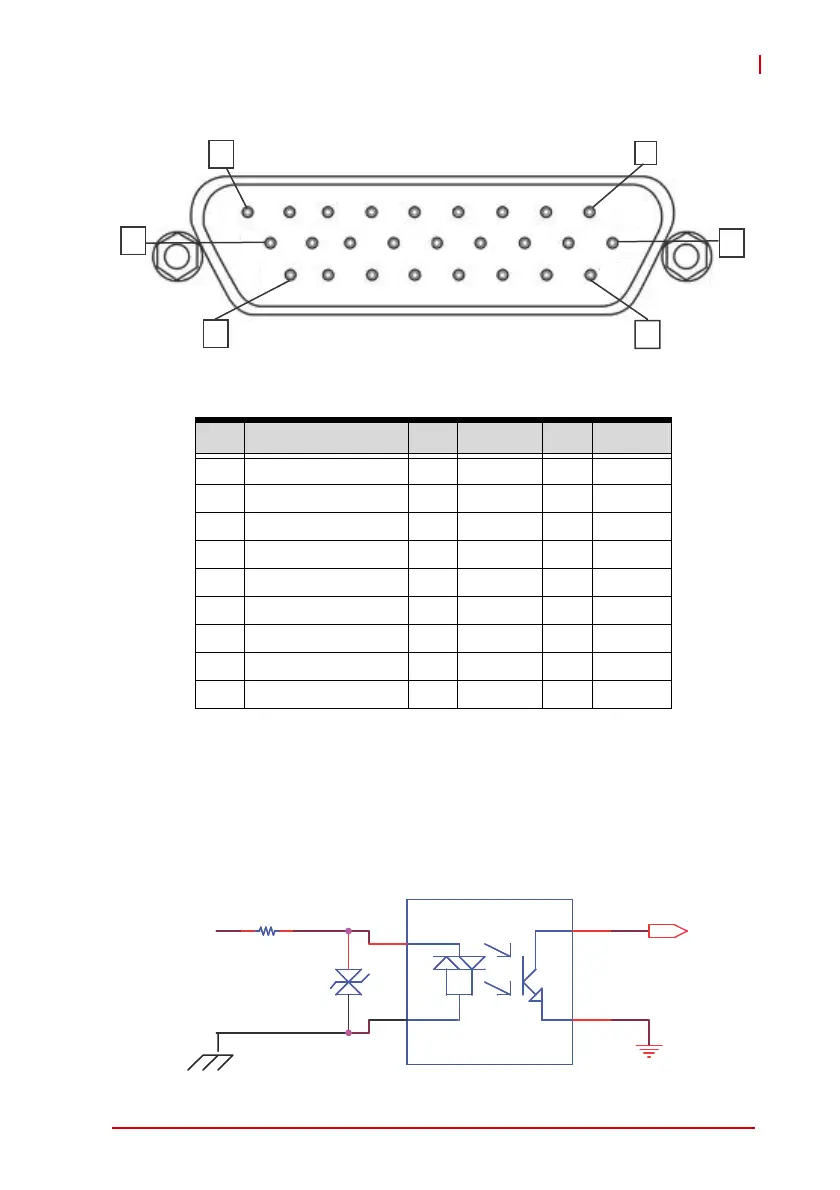
Figure 1-11: D-SUB 26P Connector on Digital I/O Port
Table 1-11: D-SUB 26P Pin Assignment on Digital I/O Port
Isolated Digital Input Circuits
The input can accept voltages up to 24V, and input resistors are
8.2KΩ. Connections between outside signals are as follows.
Figure 1-12: Isolated Digital Input Circuit
Pin Signal Pin Signa Pin Signal
1 EOGND 10 IDO_0 19 IDI_3H
2 +V5DIO_ISO 11 EOGND 20 IDI_2L
3 IDO_7 12 IDI_7H 21 IDI_2H
4 IDO_6 13 IDI_67L 22 IDI_1L
5 IDO_5 14 IDI_6H 23 IDI_1H
6 IDO_4 15 IDI_5H 24 IDI_0L
7 IDO_3 16 IDI_45L 25 IDI_0H
8 IDO_2 17 IDI_4H 26 N/C
9 IDO_1 18 IDI_3L
1
10
9
18
26
19
R67 0 8.2 K_+ -5 %08.2K_+-5%
D20
TVS
D20
TVS
1
1
2
2
1 1
2
2
4
4
3
3
IDI_nH
ISO_COM
DI
GND