Introduction 21
MXE-5400
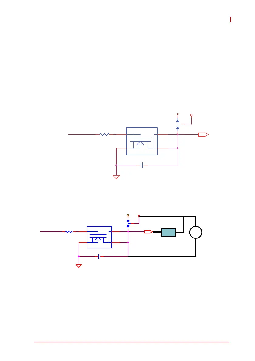
Isolated Digital Output Circuits
Each isolation digital output channel adopts a MOSFET transistor,
capable of driving peak current up to 250mA (sustained current up
to 100 mA) with voltage ranges from 5V to 35V.
The VDD pin is connected in serial with a fly-wheel diode to pro-
tect the driver during inductance loading, such as relay, motor, or
solenoid. The VDD must connect to external power to form a
fly-wheel current loop.
Figure 1-15: Isolated Digital Output Circuits
Figure 1-16: Isolated Digital Output Sample Application Circuit
+VDD
EOG ND
D29
BAV99
D29
BAV99
R682 680 R3R682 680 R3
C606 C15 N50 VKX7C606 C15 N50 VKX7
MO S F E T S i 9 9 4 5 BD Y - T 1 - G E 3 N - C HMO S F E T S i 9 9 4 5 BD Y - T 1 - G E 3 N - C H
4
4
3
3
6
6
5
5
DO_n IDO_n
EOG ND
D29
BAV99
D29
BAV99
R682 6 80R3R682 6 80 R3
C606 C15 N50 VKX7C606 C15 N50 VKX7
Q2 6B
MO SFET Si99 45 BDY -T1- GE3 N-CH
Q2 6B
MO SFET Si99 45 BDY -T1- GE3 N-CH
4
4
3
3
6
6
5
5
+
-
DC
(5 to 35V)
Load