Introduction 23
MXE-5400
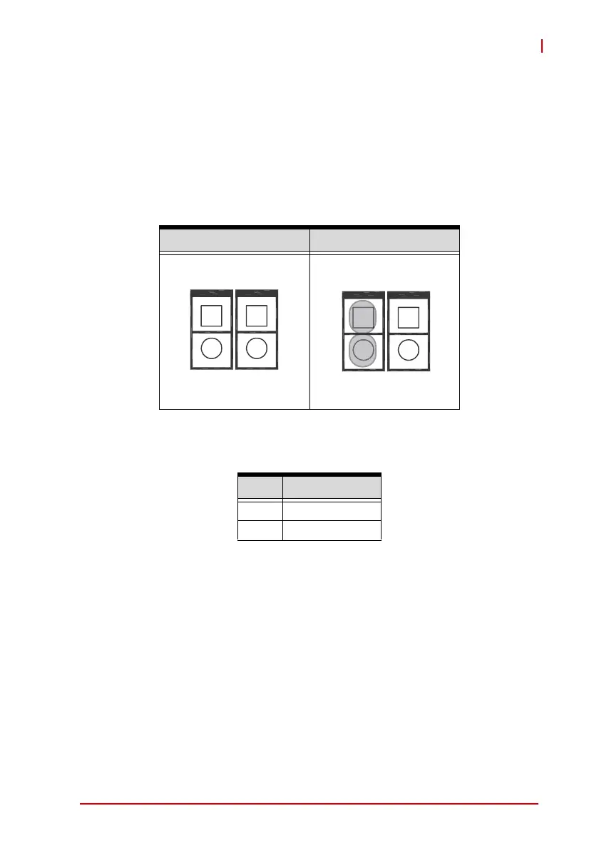
1.8.1 Clear CMOS Jumper
Under conditions in which the MXE-5400 fails to boot, clearing the
BIOS content stored in CMOS and restoring the default settings
may be effective. To clear CMOS, short Pin#1 and Pin#2 of CN3
and remove the jumper, after which the CMOS will be restored to
factory default settings.
Figure 1-18: Clear CMOS Jumper Pin Settings
Table 1-13: Clear CMOS Jumper Pin Assignment
1.8.2 DC 5V and 3.3V Connectors for GPS Module
The two power connectors, for GPS module use, carry a maxi-
mum current rating of 1A each.
Normal Clear
Pin Description
1 RTCRST#
2Gnd
CN3 CN4
1
2
1
2
CN3 CN4
1
2
1
2