Home
ADLINK Technology
Computer Hardware
MXE-5401
Page 52
ADLINK Technology MXE-5401 - Page 52
88 pages
Manual
Save Page as PDF
To Next Page
To Next Page
To Previous Page
To Previous Page
Loading...
40
Getting Started
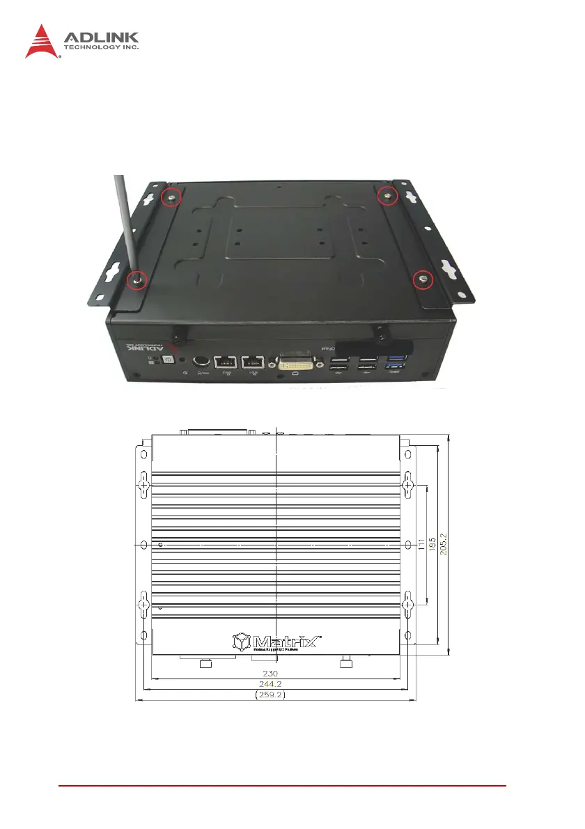
3.
F
ix the 2 wall-mount br
ackets, also included, to
the chas-
sis with the 4 inc
luded M4-P head
screws, accordin
g to
the spacin
g dimensions of th
e screw holes and br
ackets,
as shown. (All units
are in millimeters (mm)
51
53
Table of Contents
Main Page
Revision History
2
Preface
3
Table of Contents
5
List of Tables
9
List of Figures
11
1 Introduction
13
Overview
13
Features
14
Specifications
15
Unpacking Checklist
17
Figure 1-1: MXE-5400 Functional Block Diagram
17
Quick Start Guide
17
Mechanical Drawings
18
Figure 1-2: Top View
18
Figure 1-3: Front View
19
Figure 1-4: Rear View
19
Figure 1-5: (Left) Side View
19
Front Panel I/O Connectors
20
Power Button
20
Table 1-1: MXE-5400 Front Panel I/O Connector Legend
20
Figure 1-6: Front Panel I/O
20
LED Indicators
21
Reset Button
21
Table 1-2: LED Indicators
21
Dual Displayport Connector
22
Table 1-3: Displayport Pin Assignment
22
Multi-Display Option
23
DVI-I Connector
23
Table 1-4: Multi-Display Configuration
23
Table 1-5: DVI-I Connector Pin Assignment
24
Dual Gigabit Ethernet Ports
25
USB 3.0 Ports
26
Table 1-6: Gigabit Ethernet Port LED Function
26
Figure 1-7: Gigabit Ethernet Ports
26
Cfast Port
27
Rear Panel I/O Connectors
27
Figure 1-8: Rear Panel I/O
27
Table 1-7: MXE-5400 Rear Panel I/O Connector Legend
27
DB-62P COM Port and Digital I/O Connector
28
Figure 1-9: DB-62P COM Port
28
Figure 1-10: D-SUB 9P COM Connector
29
Table 1-8: DB-62P COM Port Pin Assignment
29
Table 1-10: Digital I/O Specifications
30
Table 1-9: D-SUB 9P COM Pin Assignment
30
Figure 1-11: D-SUB 26P Connector on Digital I/O Port
31
Figure 1-12: Isolated Digital Input Circuit
31
Isolated Digital Input Circuits
31
Table 1-11: D-SUB 26P Pin Assignment on Digital I/O Port
31
Figure 1-13: Isolated/Differential Digital Input Circuit
32
Figure 1-14: Isolated Digital Input Sample Application Circuit
32
Figure 1-15: Isolated Digital Output Circuits
33
Figure 1-16: Isolated Digital Output Sample Application Circuit
33
Isolated Digital Output Circuits
33
Internal I/O Connectors
34
Figure 1-17: Internal I/O
34
Table 1-12: MXE-5400 Internal I/O Legend
34
Clear CMOS Jumper
35
DC 5V and 3.3V Connectors for GPS Module
35
Figure 1-18: Clear CMOS Jumper Pin Settings
35
Table 1-13: Clear CMOS Jumper Pin Assignment
35
Figure 1-19: DC 5V and 3.3V Connectors Configuration
36
SATA Connectors (X2)
36
Table 1-14: DC 5V and 3.3V Connectors Pin Assignments
36
USIM Port
36
Figure 1-20: Mini-Pcie Connector Jumper Settings
37
Mini-Pcie Connectors
37
Extendable Power/Reset/Led
38
Figure 1-21: Extendable Power/Reset/Led Configuration
38
Table 1-15: Extendable Power/Reset/Led Connectors Pin Assignments
38
2 Getting Started
39
Installing Hard Disk Drives
39
Installing a Mini-Pcie Device
43
Internal USB Connector
45
Installing Cfast Card
46
COM Ports and DIO Device
48
Connecting DC Power
50
Wall-Mounting the MXE-5400
50
Cooling Considerations
53
3 Driver Installation
55
Installing the Chipset Driver
55
Installing the Graphics Driver
56
Installing the Ethernet Driver
56
Installing the Audio Driver
57
Installing the SEMA Utility, WDT and DI/O Drivers
57
A Appendix: Watchdog Timer (WDT)
59
DI/O Function Libraries
59
WDT with Api/Windows
59
Initwdt
59
Setwdt
60
DI/O with Api/Windows
62
Gpio_Init
62
Gpi_Read()
62
Gpo_Write()
63
Gpo_Read()
63
B Appendix: BIOS Setup
65
Main
66
BIOS Information
66
System Time/System Date
66
B.1 Main
66
Advanced
67
B.2 Advanced
67
CPU Configuration
68
Memory Configuration
70
Onboard Device Configuration
71
Advanced Power Management
73
Table B-1: Restore on Power Loss Settings
73
SATA Configuration
74
Serial Port Console Redirection
75
AMT Configuration
76
Intel® Rapid Start Technology
77
Trusted Computing Configuration
78
System Management (SEMA)
79
Chipset
80
B.3 Chipset
80
Boot
81
Boot Configuration
81
B.4 Boot
81
Boot Option Priorities
82
Security
82
Exit
83
B.6 Exit
83
Important Safety Instructions
85
Getting Service
87
Related product manuals
SMARC LEC-MTK-I1200
59 pages
DLAP-301 Series
39 pages
arm AMPERE COM-HPC-ALT
72 pages
ADLINK Technology VPX3-TL BIOS
80 pages