Optional parallel contact with J5-13 for heater
power.
120 V. A.C.J5-4,5 (5th & 6th
terminal)
J5-15
Drive motor voltage. Press STOP and then
START to make sure motor is running. (Only
runs for 2 minutes if no demand.) Lights
neon N3 when green E3 is lit. If N3 not lit
check fuse F4.
120 V. A.C.J5-4,5 (5th & 6th
terminal)
J5-14
Heater voltage to heat element. Lights N4
neon when heater is powered. Proportional
band control. Full on when far from set point
while only quick pulses when near set point.
Check fuse F5 if N4 does not light when
amber E4 lights. Turn off machine and
unplug J5 to check heat cartridge resistance if
no heat and light comes on. Should be 17
ohms between J5-13 and J5-4,5 or at heater
plug underneath frame.
120 V. A.C.J5-4,5 (5th & 6th
terminal)
J5-13
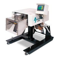
7.4 Wiring Tab (Point to Point)
The following point to point listing is provided to further assist is trouble shooting the wiring of the
T-1000.
SEAL BAR IN
(2 PIN MOLEX)
PLC INPUT PIN 14WHT/GRNBLK
PLC INPUT PIN 23WHT/BLK/BLBLK
JAW OPEN (2 PIN MOLEX)
IF/BD-J1 PIN 7ORGBLK
IF/BD-J4 PIN 1YELBLK
JAM DETECT (2 PIN MOLEX)
PIN 13 PLC INPUTWHT/GRNBLK
PIN 19 PLC INPUTPINKBLK
HEATER BAR (2 PIN MOLEX)
IF/BD-J5 PIN-6WHITEBLK
IF/BD-J5 PIN-14PURPLEBLK
THERMOCOUPLE (2 PIN CONN.)
IF/BD-J2 PIN-3REDNEG-
IF/BD-J2 PIN-2WHITEPOS+
BRAKE (SCREW CONN)
IF/BD-J5 PIN-11PURPLEWIR-2
IF/BD-J5 PIN-10PURPLEWIR-1
CLUTCH (SCREW CONN)
IF/BD-J5 PIN-8GRAYWIR-2
IF/BD-J5 PIN-6GRAYWIR-1
139