AIMB-785 User Manual 6
1.5 Board Layout: Jumper and Connector
Locations
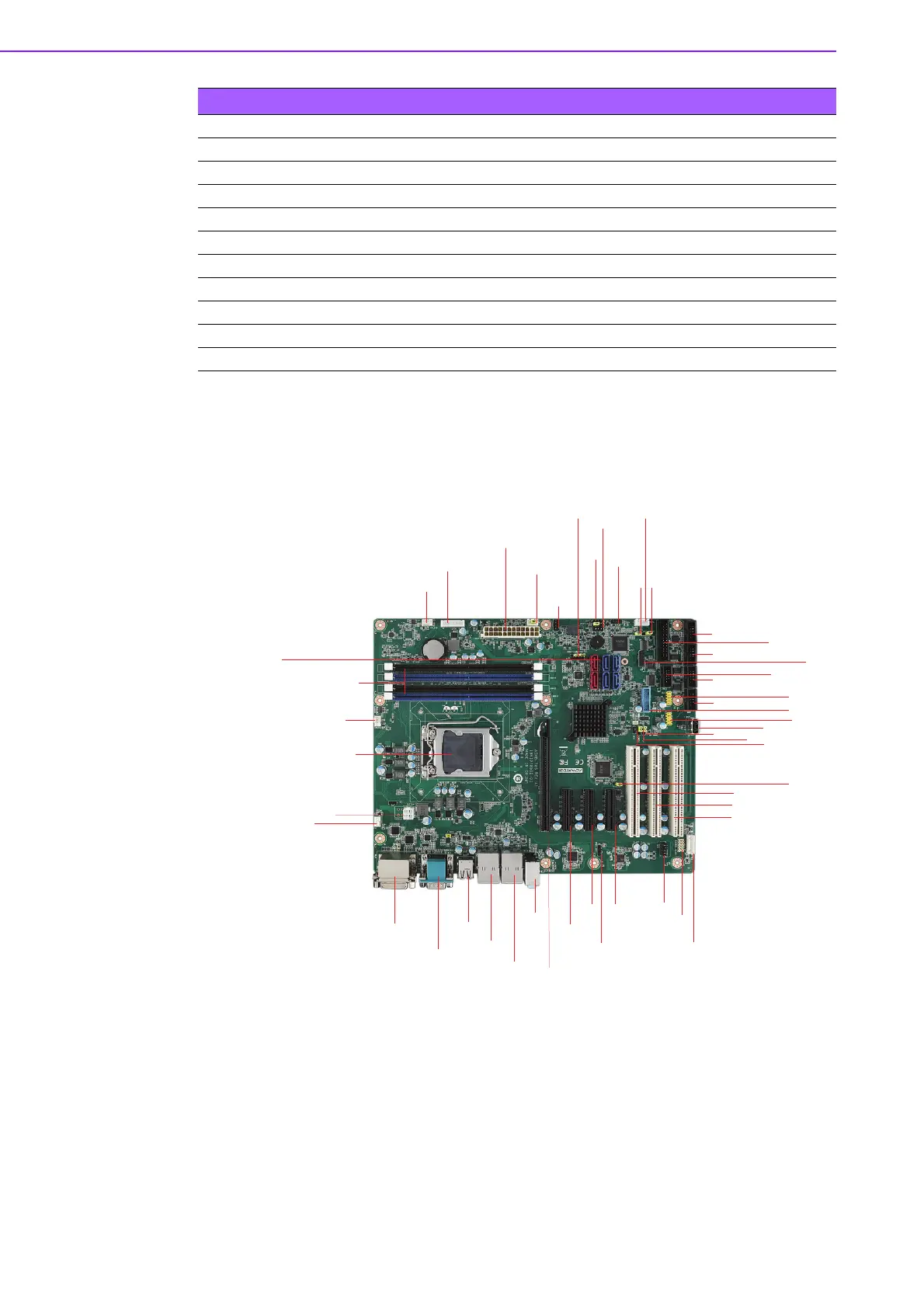
Figure 1.1 Jumper and Connector Locations
PCI3 PCI slot 3
DIMMA1 Channel A DIMM1
DIMMA2 Channel A DIMM2
DIMMB1 Channel B DIMM1
DIMMB2 Channel B DIMM2
SPI_CN1 Update BIOS pin header
SPDIF_OUT1 SPDIF Audio out pin header
JME1 Intel ME enable/disable
GPIO1 8 bit GPIO from super I/O
SMBUS1 SM Bus from PCH
LPC1 Low pin count connector
Table 1.2: Connectors
SPDIF_OUT1
FPAUD1
LANLED1
KBMS1
CPUFAN1
SYSFAN2
SYSFAN1
VOLT1
ATX12 V2
EATXPWR1
PSON1
SPI_CN1
JIR1+JWDT1+JOBS1
JFP3
JFP1+JFP2
GPIO1
SMBUS1
JCASE1
JCASEOP_ SW1
LPC1
CPU1
DVI1+DVI2
VGA1+ COM1
USB78
LAN1_USB12
LAN2_USB34
AUDIO1
AUDIO2
PCIe x16
PCIe x4
PCIe x4
PCIe x4
PCI1
PCI2
PCI3
DIMM B2
DIMM B1
DIMM A2
DIMM A1
LPT1
COM3
COM4
COM6
COM5
COM2
USB910
USB56
USB1314
USB11
JPCICLK1
JUSB_2
JCMOS1
JME1
SATA0 SATA2 SATA4
SATA1 SATA3 SATA5