Home
Advantech
Motherboard
AIMB-785G2-00A2
Page 68 (3.2.3.4 Memory Configuration)
Advantech AIMB-785G2-00A2 - 3.2.3.4 Memory Configuration; Figure 3.38 Memory Configuration
116 pages
Manual
Save Page as PDF
To Next Page
To Next Page
To Previous Page
To Previous Page
Loading...
AIMB-785 Us
er Manual
58
Detect Non-compliance device
Detect Non-Compliance PCI express Device in PEG
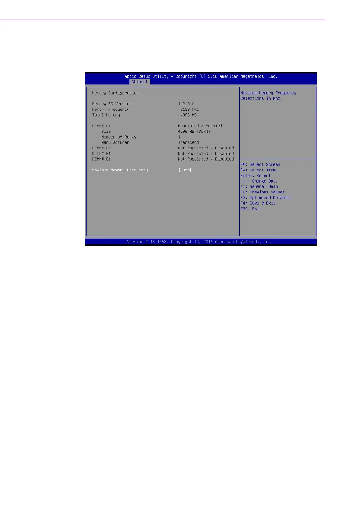
3.2.3.4
Memory Configuration
Figure 3.38 Memory
Configuration
Maximum Memory Frequency
Maximum memory frequency selections in
Mhz.
67
69
Table of Contents
Main Page
AIMB-785
1
Contents
7
1 Hardware Configuration
11
1.1 Introduction
12
1.2 Features
12
1.3 Specifications
13
1.3.1 System
13
1.3.2 Memory
13
1.3.3 Input/Output
13
1.3.4 Graphics
14
1.3.5 Ethernet LAN
14
1.3.6 Industrial Features
14
1.3.7 Mechanical and Environmental Specifications
14
1.4 Jumpers and Connectors
14
Table 1.1: Jumper list
14
Table 1.2: Connectors
15
1.5 Board Layout: Jumper and Connector Locations
16
Figure 1.1 Jumper and Connector Locations
16
Figure 1.2 I/O connectors
17
1.6 AIMB-785 Block Diagram
17
Figure 1.3 AIMB-785 Block Diagram
17
1.7 Safety Precautions
18
1.8 Jumper Settings
18
1.8.1 How to set jumpers
18
1.8.2 CMOS clear & ME clear (JCMOS1 & JME1)
19
Table 1.3: JCMOS1/JME1
19
1.8.3 Watchdog timer output (JWDT1)
19
Table 1.4: Watchdog timer output (JWDT1)
19
Table 1.5: ATX/AT mode selector (PSON1)
20
Table 1.6: JUSB
20
Table 1.7: JPCICLK1
20
1.9 System Memory
21
1.10 Memory Installation Procedures
21
1.11 PCI Bus Routing Table
21
2 Connecting Peripherals
23
2.1 Introduction
24
2.2 Parallel Port (LPT1)
24
2.3 USB Ports and LAN Ports (LAN1_USB910, LAN2_USB12, USB3, USB56, USB78, USB1112 & USB1314)
25
2.4 VGA Connector and DVI-D Connector (DVI1/ DVI2 + VGA1)
26
2.5 Serial Ports (COM1, COM2, COM3, COM4, COM5 & COM6)
26
2.6 External Keyboard & Mouse (KBMS1)
27
2.7 CPU Fan Connector (CPUFAN1)
27
2.8 System FAN Connector (SYSFAN1 and SYSFAN2)
28
2.9 Front Panel Connectors (JFP1, JFP2 & JFP3)
28
2.9.1 Power LED and Keyboard Lock (JFP3)
29
Table 2.1: PS/2 or ATX power supply LED status
29
2.9.2 External Speaker (JFP2 pins 1, 4, 7 & 10)
29
2.9.3 HDD LED Connector (JFP2 pins 2 & 5)
29
2.9.4 SNMP SM_Bus connector (JFP2 pins 8 & 11)
29
2.9.5 ATX Soft Power Switch (JFP1 pins 3 & 6)
29
2.9.6 Reset Connector (JFP1 pins 9 & 12)
29
2.10 Line Out, Mic In Connector (AUDIO1_AUDIO2)
30
2.11 8-pin Alarm Board Connector (VOLT1)
30
2.12 Case Open Connector (JCASE1)
31
2.13 Front Panel LAN Indicator Connector (LANLED1)
31
Table 2.2: Front Panel LAN Indicator Connector
31
2.14 Serial ATA Interface (SATA0~5)
32
2.15 PCI Slots (PCI1 ~ PCI3)
32
2.16 PCIe x16 Expansion Slot (PCIEX16_1)
33
2.17 PCIEX4_1 ~ PCIEX4_3
33
2.18 Auxiliary 4-pin power connector (ATX12V1)
34
2.19 SPI Flash Connector (SPI_CN1)
34
2.20 Low Pin Count Connector (LPC1)
35
Table 2.3: Advantech LPC Module List
35
3 BIOS Operation
37
3.1 Introduction
38
Figure 3.1 Main setup screen
38
3.2 Entering BIOS Setup
39
3.2.1 Main Menu
39
Figure 3.2 Main setup screen
39
3.2.2 Advanced BIOS Features Setup
40
Figure 3.3 Advanced BIOS features setup screen
40
3.2.2.1 Platform Misc Configuration
41
Figure 3.4 Platform Misc Configuration
41
3.2.2.2 CPU Configuration
42
Figure 3.5 CPU Configuration
42
3.2.2.3 Power & Performance
43
3.2.2.4 PCH-FW Configuration
44
Figure 3.6 PCH-FW Configuration
44
Figure 3.7 AMT Configuration
45
Figure 3.8 CIRA Configuration
45
Figure 3.9 ASF Configuration
46
Figure 3.10 Secure Erase Configuration
47
Figure 3.11 OEM Flags Settings
47
Figure 3.12 MEBx Resolution Settings
48
3.2.2.5 Trusted Computing
49
Figure 3.13 TPM Settings
49
3.2.2.6 ACPI Settings
50
Figure 3.14 ACPI Settings
50
3.2.2.7 SMART Settings
51
Figure 3.15 SMART Settings
51
3.2.2.8 Super IO Configuration
52
Figure 3.16 Super IO Configuration
52
Figure 3.17 Serial Port 1 Configuration
52
Figure 3.18 Serial Port 2 Configuration
53
Figure 3.19 Parallel Configuration
53
3.2.2.9 H/W Monitor
54
Figure 3.20 PC Health Status
54
3.2.2.10 Second Super IO Configuration
55
Figure 3.21 Super IO Configuration
55
Figure 3.22 Serial Port 3 Configuration
56
Figure 3.23 Serial Port 4 Configuration
57
Figure 3.24 Serial Port 5 Configuration
57
Figure 3.25 Serial Port 6 Configuration
58
3.2.2.11 S5 RTC Wake Settings
59
Figure 3.26 S5 RTC Wake Settings
59
3.2.2.12 Serial Port Console Redirection
60
Figure 3.27 Serial Port Console Redirection
60
3.2.2.13 Intel TXT Information
61
Figure 3.28 Intel TXT Information
61
3.2.2.14 PCI Subsystem Settings
61
Figure 3.29 PCI Subsystem Settings
61
3.2.2.15 CSM Configuration
62
Figure 3.30 CSM Configuration
62
3.2.2.16 USB Configuration
63
Figure 3.31 USB Configuration
63
3.2.3 Chipset
64
Figure 3.32 Chipset
64
3.2.3.1 System Agent (SA) Configuration
64
Figure 3.33 System Agent (SA) Configuration
64
3.2.3.2 Graphics Configuration
65
Figure 3.34 Graphics Configuration
65
Figure 3.35 LCD Control
66
3.2.3.3 PEG Port Configuration
67
Figure 3.36 PEG Port Configuration
67
Figure 3.37 PEG Port Feature Configuration
67
3.2.3.4 Memory Configuration
68
Figure 3.38 Memory Configuration
68
3.2.3.5 PCH-IO Configuration
69
Figure 3.39 PCH-IO Configuration
69
3.2.3.6 PCI Express Configuration
70
3.2.3.7 SATA Configuration
72
Figure 3.40 SATA Configuration
72
3.2.3.8 USB Configuration
73
3.2.3.9 HD Audio Configuration
73
3.2.4 Security
74
Figure 3.41 Security
74
3.2.5 Boot
75
Figure 3.42 Boot
75
3.2.6 Save & Exit
76
Figure 3.43 Save & Exit
76
4 Chipset Software Installation Utility
77
4.1 Before you begin
78
4.2 Introduction
78
4.3 Windows 10 / Windows 8.1 / Windows 7 Driver Setup
79
5 Integrated Graphic Device Setup
81
5.1 Introduction
82
5.2 Windows 10/Windows 8.1/Windows 7 Driver Setup
82
6 LAN Configuration
83
6.1 Introduction
84
6.2 Features
84
6.3 Installation
84
6.4 Win 10/Win 8.1/Win 7 Driver Setup (LAN)
84
7 Intel ME
85
7.1 Introduction
86
7.2 Installation
86
8 Intel USB 3.0
87
8.1 Introduction
88
8.2 Installation
88
9 SATA RAID Setup
89
9.1 Introduction
90
9.2 SATA RAID Driver and Utility Setup
90
10 HD Audio
91
10.1 Introduction
92
10.2 Installation
92
A Programming the Watchdog Timer
93
A.1 Watchdog timer overview
94
A.2 Programming the Watchdog Timer
94
Table A.1: Watchdog timer registers
96
A.2.1 Example Programs
96
B I/O Pin Assignments
101
B.1 Parallel Port (LPT1)
102
Table B.1: Parallel Port (LPT1)
102
B.2 USB2.0 Type A Port (USB3)
102
Table B.2: USB2.0 Type A Port (USB3)
102
B.3 USB3.0 Header (USB1314)
103
B.4 USB2.0 Header (USB56, USB78, USB1112)
103
Table B.3: USB2.0 Header (USB56, USB78, USB1112)
103
B.5 VGA Connector (VGA1)
104
Table B.4: VGA Connector (VGA1)
104
B.6 DVI Interface
104
Table B.5: DVI-D Connector (DVI1/DVI2)
104
B.7 RS-232 and COM3 Interface
105
Table B.6: RS-232 Interface (Rear)
105
Table B.7: RS-232 Interface (onboard)
105
Table B.8: COM3 Interface (onboard)
105
B.8 External Keyboard and Mouse Connector (KBMS1)
106
Table B.9: External Keyboard and Mouse Connector (KBMS2)
106
B.9 Infrared (IR) connector (JIR1) and JWDT1 and HW Monitor Alarm (JOBS1)
106
Table B.10: JIR1+JWDT1+JOBS1
106
B.10 System Fan Power Connector (SYSFAN1/ SYSFAN2)
106
Table B.11: Fan Power Connector (SYSFAN1/SYSFAN2)
106
B.11 Power LED and Keyboard Lock (JFP3)
107
Table B.12: Power LED and Keyboard Lock (JFP3)
107
B.12 External Speaker Connector (JFP2)
107
Table B.13: External Speaker Connector (JFP2)
107
B.13 Reset Connector (JFP1)
107
Table B.14: Reset Connector (JFP1)
107
B.14 HDD LED Connector (JFP2)
108
Table B.15: HDD LED Connector (JFP2)
108
B.15 ATX Soft Power Switch (JFP1)
108
Table B.16: ATX Soft Power Switch (JFP1)
108
B.16 SNMP SM_BUS Bus Connector (JFP2)
108
Table B.17: SM Bus Connector (JFP2)
108
B.17 USB/LAN ports (LAN1_USB910 and LAN2_USB12)
109
Table B.18: USB2.0 Port
109
Table B.19: USB3.0 Port
109
Table B.20: Giga LAN 10/100/1000 Base-T RJ-45 port
109
B.18 Line Out, MIC IN Connector (AUDIO)
109
B.19 Front Panel Audio Connector (FPAUD1)
110
Table B.21: Front Panel Audio Connector (FPAUD1)
110
B.20 8-pin Alarm Board Connector (VOLT1)
110
Table B.22: 8-pin Alarm Board Connector (VOLT1)
110
B.21 Case Open Connector (JCASE1)
111
Table B.23: Case Open Connector (JCASE1)
111
B.22 Front Panel LAN LED Connector (LAN_LED1)
111
Table B.24: LAN LED Connector (LANLED1)
111
B.23 SPI_CN1: SPI Flash Card Pin Connector
111
Table B.25: SPI_CN1:SPI fresh card pin connector
111
B.24 Fixed I/O Ranges Decoded by Intel PCH
112
Table B.26: Fixed I/O Ranges Decoded by PCH
112
B.25 System I/O Ports
114
B.26 DMA Channel Assignments
114
Table B.27: DMA channel assignments
114
B.27 Interrupt Assignments
115
Table B.28: Interrupt assignments
115
B.28 1st MB Memory Map
115
Table B.29: 1st MB memory map
115
Related product manuals
Advantech AIMB-785
116 pages
Advantech AIMB-780
108 pages
Advantech AIMB-784
114 pages
Advantech AIMB-742
124 pages
Advantech AIMB-763
66 pages
Advantech AIMB-275
142 pages
Advantech AIMB-581
112 pages
Advantech AIMB-240 Series
99 pages
Advantech ASMB-585
122 pages
Advantech ASMB-785
128 pages
Advantech ASMB-784
112 pages
Advantech SIMB-982
68 pages