13 EKI-1500 Series User Manual
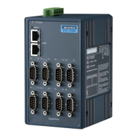
The following view is valid for the EKI-1524.
Figure 2.9 Top View
2.3.4 LED Indicators
Figure 2.10 System LED Panel
2.3.5 Dimensions
The following view is valid for the EKI-1521.
Figure 2.11 Dimensions
No. Item Description
1 Terminal block Connect cabling for power and alarm wiring
2 Ground terminal Screw terminal used to ground chassis
3 Wall mounting holes Screw holes (x4) used in the installation of a wall mounting plate
PWR2
P-Fail
DC12-48V
PWR1
V2- V2+ V1- V1+
1A@24V
No. LED Name LED Color Description
1 P1 Green Power 1 is on
Off Power 1 is off, or power error condition exists
2 P2 Green Power 2 is on
Off Power 2 is off, or power error condition exists
3 Status Amber The device server has been located by utility’s loca-
tion function
Amber, blinking System is ready (1cycle/sec.)
Off System is not working
140 [5.512]
140 [5.512]
149.80 [5.898]
47.05 [1.852]
47.95 [1.888]
95 [3.740]
104 [4.094]
95 [3.740]
95 [3.740]
30 [1.181]
68 [2.677] 39 [1.535]

 Loading...