15
IHBI. 1011. 4138500_00
drawing referred to the unit HBI080C - HBI100C
the image is purely indicative
Gas
Liquido
Unità esterna
Unità interna
A
B
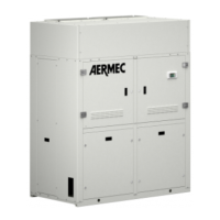
The outdoor unit must be installed near
to the indoor unit in order to reduce the
length and the curves of the cooling
pipes.
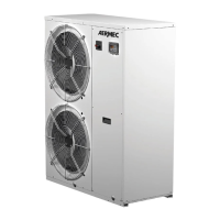
ELECTRIC CONNECTIONS TO THE OUTDOOR UNIT
- Remove the terminal board cover panel.
- Connect the cables to the unit clamps as indicated in the wiring diagrams. Pay attention that every cable is connected
correctly to the terminal boards of the two units.
- Re-position the terminal board cover panel.
INPUT CABLES
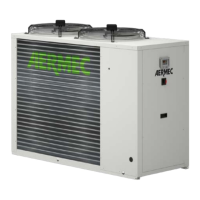
Precautions for installation of the outdoor
unit:
• Use M12 bolts to tighten the feet and
the sub-frame during installation.
• The outdoor unit must be installed
on a solid base measuring 10 cm in
height
• The requisites for the installation
clearance of the unit body are dem-
onstrated in the following layout.
• The outdoor unit must be lifted act-
ing on the relevant hole.
Protect the unit during lifting.
Do not strike metal parts, to prevent the
formation of rust.
OUTDOOR
INDOOR
9. SPACE REQUISITES FOR INSTALLATION OF THE OUTDOOR UNIT
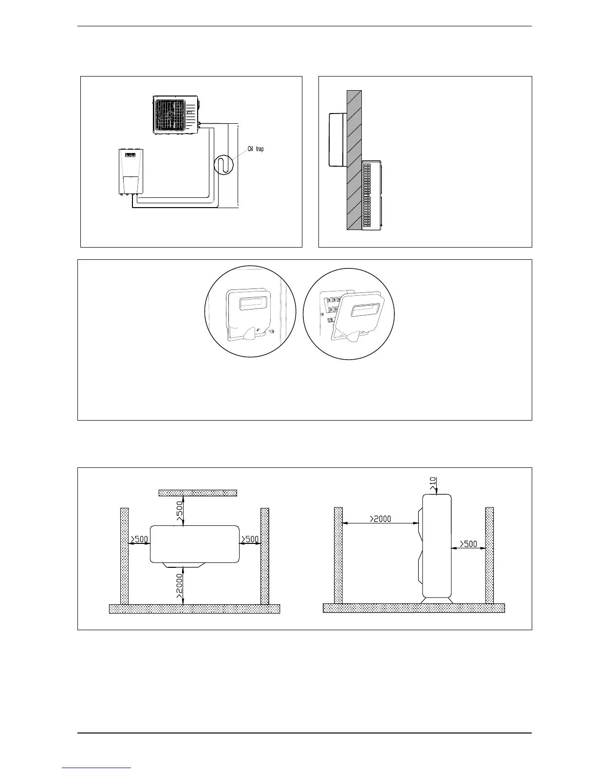
If the outdoor unit is positioned in a higher point with
respect to the indoor unit, realise a siphon in order to pre-
vent the deposit of oil.