31
IHBI. 1011. 4138500_00
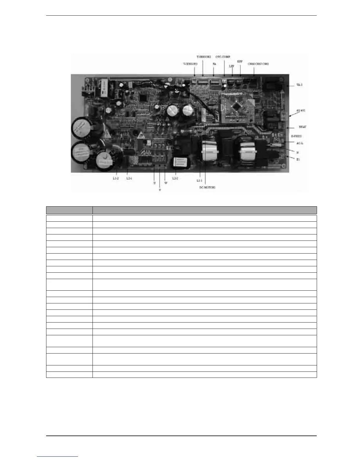
24. WIRING DIAGRAM
COMPONENTS SPECIFICATIONS
HBI080C - HBI100C
AC-L live wire input of power supply, red
N zero wire input of power supply, white
E1 ground wire, yellow green
L2-2 PFC blue inductive wire
L1-1 PFC brown inductive wire
L2-1 PFC yellow inductive wire
L1-2 PFC white inductive wire
U U-phase of compressor
V V-phase of compressor
W W-phase of compressor
DC_MOTOR1
DC fan
1 pin: strong power supply 3 pin fan GND 4 pin+15V 5 pin control signal 6 pin feedback signal;
4V 4V1 4-way valve
HEAT electric heating tape
VA-1 e-heater of chassis
HPP high pressure switch
LPP low pressure switch
OVC-COMP overload protection of compressor
T-SENSOR2 1, 2 hole pipe temperature 3, 4 hole environment 5, 6 hole exhaust
TSENSOR3
1 hole: +3.3V
2 hole: detection ; suction temperature sensor
CN66 CN67 communication cable 2 pin B 3pinA
CN65
communication cable: 1 pin earthed 2 pin B 3 pin A 4 pin+12power supply; It can not be used for com-
munication between outdoor unit and indoor unit;
FA pipe electric expansion valve 1-4 pin driving impulse output 5 pin +12V
H-PRESS signal input of pressure sensor 1 pin GND 2 pin signal input 3 pin +5V