26
HBI. 1011. 4138500_00
The 3-way valve is necessary to use the DHW tank. Its task is to divert the fl ow between the fl oor heating circuit and the heating circuit of
the water tank.
Type Power Operational mode Supported
SPDT with 3 cables 230V 50Hz
~
AC
Select “Flow A” between “Flow
A” and “Flow B”
YES
Select “Flow B” between “Flow
B” and “Flow A”
YES
(1) : SPDT =Single pole, double contact. The three cables are made up from Live 1 (to select Flow B) and Neutral (for the common).
(2) : Flow A indicates the ‘fl ow of water from the indoor unit to the fl oor hydraulic circuit’.
(3) : Flow B indicates the ‘fl ow of water from the indoor unit to the DHW tank’.
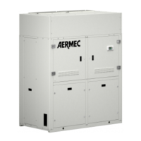
How to connect the 3-way valve: follow the procedures below (Phase 1 ~ Phase 2).
Phase 1. Remove the front lid of the indoor unit and open the control box.
Fase 2. Connect the 3-way valve cable as indicated below.
WARNING:
The 3-way valve must select the water tank circuit when
the electric current is fed to the cable (OFF) and to cable
(N).
The 3-way valve must select the fl oor circuit when the
electric current is fed to the cable (ON) and to cable (N).
(OFF) : Line signal (water tank heating) from the printed
circuit to the 3-way valve.
(ON) : Line signal (fl oor heating) from the printed circuit to
the 3-way valve.
(N) : Neutral signal from the printed circuit to the 3-way
valve.
12
0111
7
8
9
OFF
ON
N
OFF
ON
N
2 way value 1 2w way value 2
!
20.4. THREE-WAY VALVE (NOT SUPPLIED)
!
Currently not available
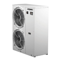
20.5. INSTALLATION OF AUXILIARY DEVICE (GATE CONTROLLER) - (NOT SUPPLIED)
If the door control function is present, extract the main
cable 50 on the board for XT2 terminals between 19 and
20 and then connect the door control device according
to installation guide.
20 19 20 19
XT2
50
Operations to be performed in order to
install an auxiliary control device on the
XT2 board:
1. Remove the cable (jumper) n° 50
from clamps n° 19 - 20
2. Connect the auxiliary device in your
possession (following the instructions
supplied) to the clamps n° 19 - 20.