21
IHBI. 1011. 4138500_00
WATER EXPANSION FACTOR AT DIFFERENT TEMPERATURES
Temperature (°C) Expansion factor (e)
0 0.00013
40
10 0.00027
20 0.00177
30 0.00435
40 0.00782
45 0.0099
50 0.0121
55 0.0145
60 0.0171
65 0.0198
70 0.0227
75 0.0258
80 0.029
85 0.0324
90 0.0359
95 0.0396
100 0.0434
SELECTING THE EXPANSION VESSEL:
Formula:
V = Volume of the expansion vessel
c = Total volume of the water
p
1
= Expansion vessel pre-load pressure
p
2
= Maximum pressure during system functioning
(i.e. safety valve activation pressure).
e = Water expansion factor (the differnce between
the original water temperature expansion factor
and that of the highest water temperature).
V =
c
.
e
1-
1+p
1
1+p
2
16. PROCEDURES FOR THE REALISATION OF THE COOLING LINES
Procedure for the preparation of the fl ared fi t-
tings:
The cooling lines and the HBI unit are real-
ised using fl ared connections
Flared connections: used in the tracts
connected directly to the refrigerant con-
nections (gas and liquid lines) of the out-
door or indoor units;
The procedure for the realisation of a
fl ared connection is as follows:
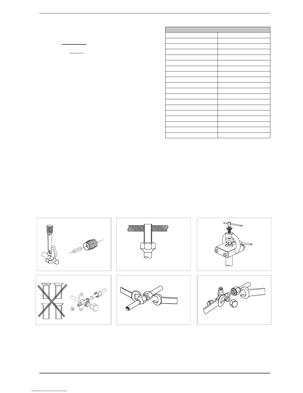
• cut the copper pipes to measure-
ment using the pipe-cutter and
smooth the ends using a pipe debur-
rer (Fig. A);
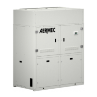
• isolate the pipes and insert the ta-
pered nuts before fl aring (Fig. B);
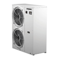
• for fl aring use a tapered fl aring tool
(Fig. C);
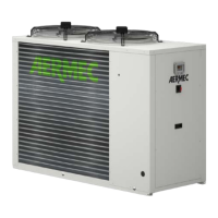
• check that the tapered surface is in
axis with the pipe, smooth, without
cracks and even thickness (Fig. D).
• connect the lines with the fl ared con-
nections
Fig. C
Fig. E
Fig. A Fig. B
Fig. D
Fig. F