22
HBI. 1011. 4138500_00
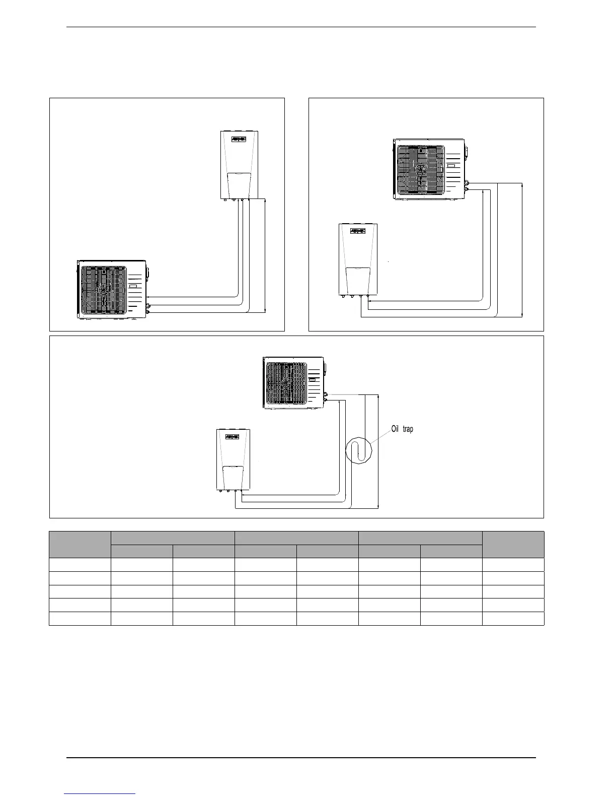
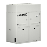
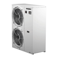
17. COOLING LINES CONNECTION LAYOUT
Model
Pipe dimension (ø) Length B Height A
Additional
refrigerant
Gas Liquid Standard Max Standard Max
HBI080 5/8” 3/8” 7.5m 30m 0m 15m 50g/m
HBI100 5/8” 3/8” 7.5m 30m 0m 15m 50g/m
HBI120 5/8” 3/8” 7.5m 30m 0m 15m 50g/m
HBI140 5/8” 3/8” 7.5m 30m 0m 15m 50g/m
HBI160 5/8” 3/8” 7.5m 30m 0m 15m 50g/m
NOTES:
1. Refrigerant does not have to be added when
the length of the pipe is less than 10 m. If this is not
the case, add refrigerant according to that stated
in the table.
Example: if the 16kw model is installed at a dis-
tance of 25 m, 750 g of refrigerant must be add-
ed, according to the following calculation (25-
10)*50=750.
2. The nominal capacity is based on standard
pipe length, while the maximum length allowed is
based on the reliability of the product functioning.
3. The oil separator must be installed every 5-7m,
when the position of the outdoor unit is higher than
the indoor unit.
Outdoor unit
Indoor unit
A
B
A
B
Outdoor unit
Indoor unit
Outdoor unit
Indoor unit
A
B
12
3