25
IHBI. 1011. 4138500_00
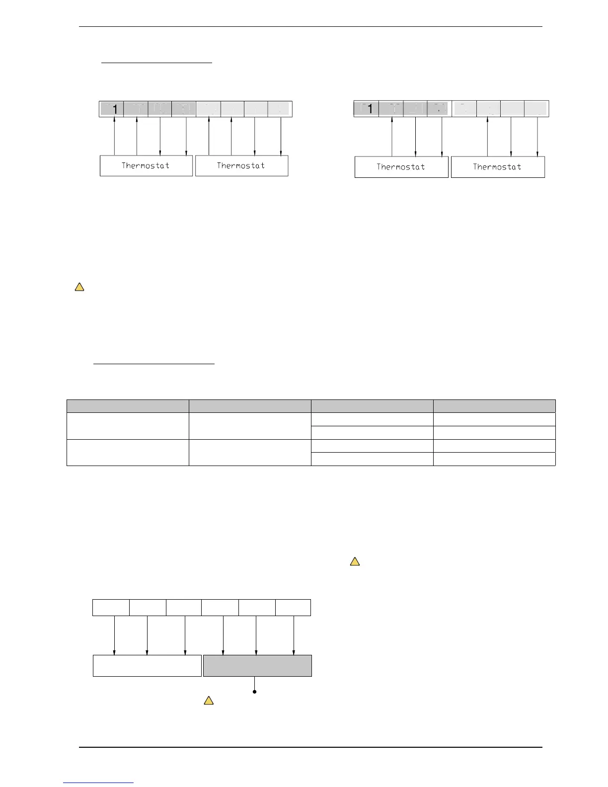
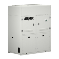
20.2. THERMOSTAT (NOT SUPPLIED)
Heating/cooling thermostat Heating thermostat only
How to connect the thermostat:
Remove the indoor unit casing and open
the control box
Identify the thermostat electric specifi ca-
tions, if 230V, fi nd the terminal board
!
WARNING:
1. NEVER USE THE 230V AC thermostat and
the 24V AC thermostat at the same time,
otherwise a short circuit will be caused and
the life-saving device will cut the electric
power supply off.
2. The thermostat temperature setting (heat-
ing or cooling) must be selected from the
temperature range set for the product.
3. For other restrictions, consult the previous
page relative to the remote air temperature
probe.
4. Do not connect external electric loads,
the (L) and (N) cables must be used only for
the electric type thermostat.
5. Do not connect external electric loads,
such as valves, fan coil units etc. If connect-
ed, the indoor unit printed circuits could be
seriously damaged.
26
425221 22
23
XT3
Heat
N
L
(230V)
27 28
Cool
Heat
N
Cool
L
(24V)
26
252421 22
23
T3
Heat
N
L
(230V)
27 28
Heat
N
L
(24V)
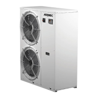
20.3. 2-WAY VALVE (NOT SUPPLIED)
The 2-way valve is necessary to control the fl ow of water during cooling. Its task is to cut-off the fl ow of water in the fl oor circuit in cooling
mode when the fan coil is set-up for cooling.
TYPE POWER OPERATIONAL MODE SUPPORTED
Normally open - 2 cables 230V 50Hz
~
AC
Closure of the flow of water YES
Opening of the flow of water YES
Normally closed - 2 cables 230V 50Hz
~
AC
Closure of the flow of water YES
Opening of the flow of water YES
(1) : Normally open type: when the electric current is NOT fed, the valve is open. (When the electric current is fed, the valve is closed).
(2) : Normally closed type: when the electric current is NOT fed, the valve is closed. (When the electric current is fed, the valve is open).
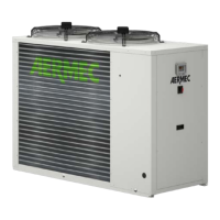
How to connect the 2-way valve: follow the procedures given below (Phase 1 ~ Phase 2).
Phase 1. Remove the front lid of the indoor unit and open the control box.
Phase 2. Find the terminal board and connect the cable as indicated below.
WARNING:
The normally open type must be connected to the ca-
ble (NO) and cable (N) so that the valve closes in cooling
mode.
The normally closed type must be connected to the ca-
ble (NC) and cable (N) so that the valve closes in cooling
mode.
(NO) : Line signal (for normally open type) from the printed
circuit to the 2-way valve.
(NC) : Line signal (for normally closed type) from the print-
ed circuit to the 2-way valve.
(N) : Neutral signal from the printed circuit to the 2-way
valve.
3
2
2 way value 1 2 way value 2
45
6
OFF
ON
N
OFF
ON
N
NC
NO
N
N
NC
NO
1
!
!
Currently not available
4