32
HBI. 1011. 4138500_00
HBI120C - HBI140C - HBI160C
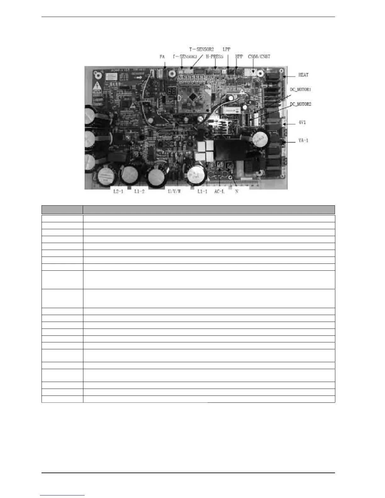
COMPONENTS SPECIFICATIONS
AC-L live wire input of power supply, red
N Neutral line input of power supplyPFC blue inductive wireblue
L1-1 PFC brown inductive wire
L2-1 PFC yellow inductive wire
L1-2 PFC white inductive wire
U U-phase of compressor
V V-phase of compressor
W W-phase of compressor
DC_MOTOR1
DC fan
1 pin strong power supply 3 pin fan GND 4 pin +15V
5 pin control signal 6 pin feedback signal
DC_MOTOR2
DC fan
1 pin strong power supply 3 pin fan GND 4 pin +15V
5 pin control signal 6 pin feedback signal
4V1 4-way valve
HEAT electric heating tape
VA-1 e-heater of chassis
HPP high pressure switch
LPP low pressure switch
T-SENSOR2 1, 2hole pipe temperature 3, 4hole environment 5, 6hole exhaust
TSENSOR3 1 hole:+3.3V sensor
2 hole: detection: suction temperature
CN66CN67 communication cable 2 pin B 3 pin A
CN65 communication cable 1 pin earthed 2 pin B 3 pin A 4 pin+12 power supply It can not be used for communi-
cation between outdoor unit
and indoor unit.
FA pipe electric expansion valve 1-4 pin driving impulse output 5 pin +12V
H-PRESS signal input of pressure sensor 1 pin GND 2 pin signal input 3 pin +5V