36
HBI. 1011. 4138500_00
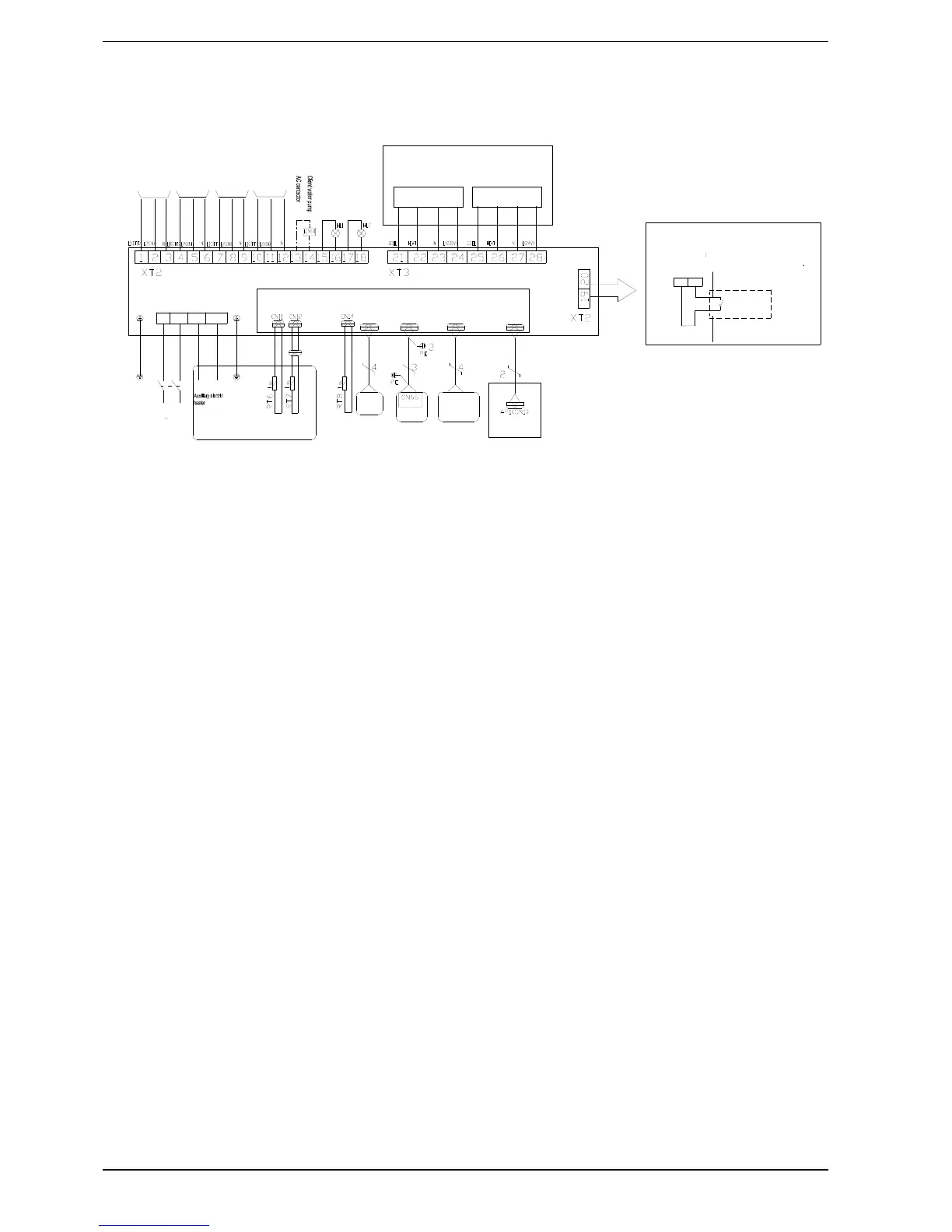
Wiring diagram: Indoor and outdoor unit (including wiring on site)
Error
indicating lamp
Running
indicating lamp
XT2
Inside Unit
Electric Box
LN 1
N(2)
XT1
Water tank
L
N
LK
POWER
230V 50HZ
Display
board
CN16 CN5
AP
2-way
valve1
2-way
valve2
3-way
valve1
3-way
valve2
Water-tank
temp sensor2
Water-tank
temp sensor1
Outdoor
Unit
PE
Main Baord
CN14
Remote air
temp sensor
Long-distance
monitor PC
CN7
Other thermal system
Water- out temp sensor
PE
Thermostat Thermostat
Power supply for Thermostat:If it is 230V AC,please
connect Terminal block(xt3) 21.22.23.24;If it is 24V
AC, please connect Terminal block(xt3) 25.26.27.28.
They are can not be connected as the same time.
,IWKHUHLVJDWHFRQWUROIXQFWLRQ
SXOORXWWKHOHDGLQJZLUHRQ
WHUPLQDOERDUG
;7EHWZHHQDQG
DQGWKHQFRQQHFWWKH*DWHFRQWUROOHU
Gate-controller
20 19
Specifi cation:
1- The functioning LED (HL1) and the error LED (HL2) are connected or not connected on customer request.
2-Contactor AC water pump reviews (KM4) will be a standby pump in the future so it should not be connected.
3- The differential switch (LK) is necessary for further installations.