Establishing the image geometry reference values for general
radiography applications
To establish the image geometry reference values, proceed as follows:
1. Print the QC general radiography test image or use the previously printed
test image.
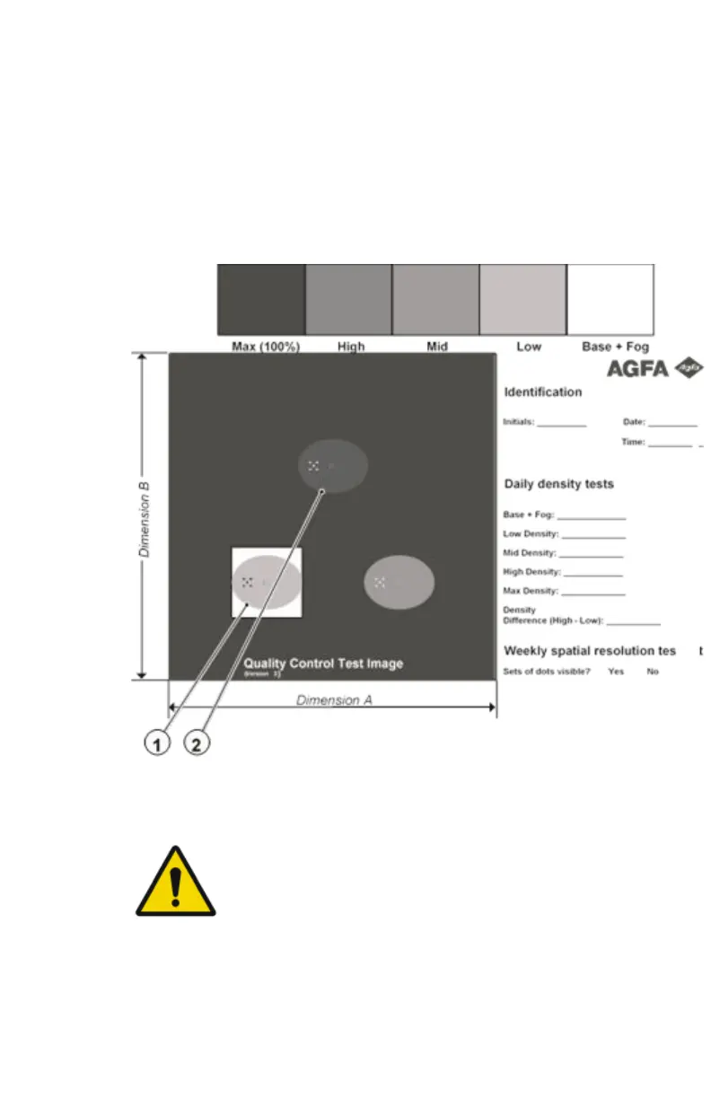
You should obtain an image looking like this (without the dimensions A
and B):
Figure 8: QC general radiography test image
2. To determine the reference values for geometry, measure the distances A
and B of the geometric square on the test image.
WARNING:
Make sure to measure distance A from the left edge of
the left line to the right edge of the right line and
distance B from the upper edge of the upper line to the
lower edge of the lower line.
We strongly recommend using a 30 cm (12 inch) machinist
scale with 0.5 mm divisions (1/64 inch).
3. Record these values as reference dimensions A
ref
and B
ref
on Chart 4
(‘Geometric Consistency Control Chart’).
92
| Drystar 5500, Drystar 5503 | Advanced Operation (key-operator mode)
2901J EN 20191018 0826