255
Chapter 5 Tutorial
Attributes of AC Signals
4
5
The RMS value of a waveform also represents the one-cycle average
power in the signal, minus the power in any DC component of the signal.
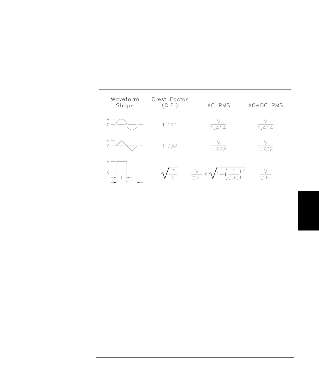
Crest factor is the ratio of a signal’s peak value to its RMS value and will
differ according to waveshape. The table below shows several common
waveforms with their respective crest factors and RMS values.
Note. If an average-reading voltmeter is used to measure the “DC
voltage” of a waveform, the reading may not agree with the DC Offset
setting of the waveform generator. This is because the waveform may have
a non-zero average value that would be added to the DC Offset.
You may occasionally see AC levels specified in “decibels relative to
1 milliwatt” (dBm). Since dBm represents a power level, you will need to
know the signal’s RMS voltage and the load resistance in order to make
the calculation.
dBm = 10 x log
10
(P / 0.001) where P = V
RMS
2
/R
L
 Loading...