Microwave Switch/Attenuator Driver 8
34980A User’s Guide 207
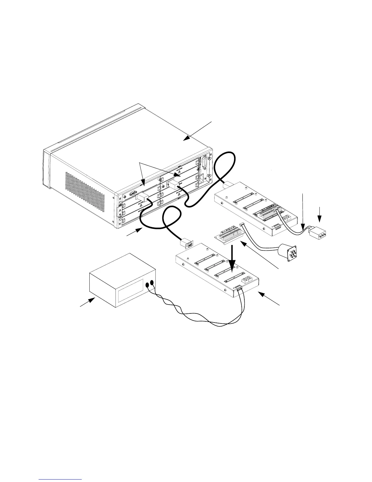
A system configuration is illustrated below. As shown, two driver interface
modules are used, one in slot 1 and one is slot 6. Each driver interface is
connected to a single remote module. The remote module attached to
slot 1 uses an external power supply. The remote module attached to
slot 6 is using the internal power supply.
• The first remote module is connected to the driver interface using
the provided D- Sub cable. This cable is a fully populated RS- 232
extension cable.
• Although only a single distribution board is show in the figure for each
remote, each remote module may have up to four distribution boards
connected.
• The driver interface can supply 24 V power to the first remote
module only.
• The first remote module may also use an external power source.
• Each remote module only supports a single power source.
24 Volts
34945EXT Remote Module
Distribution Board
Switch
Switch Cable
34945A Driver
Interface Module
34980A Mainframe
D-Sub Cable (RS-232 Extension)
External Power Supply
 Loading...


