208 34980A User’s Guide
8 Microwave Switch/Attenuator Driver
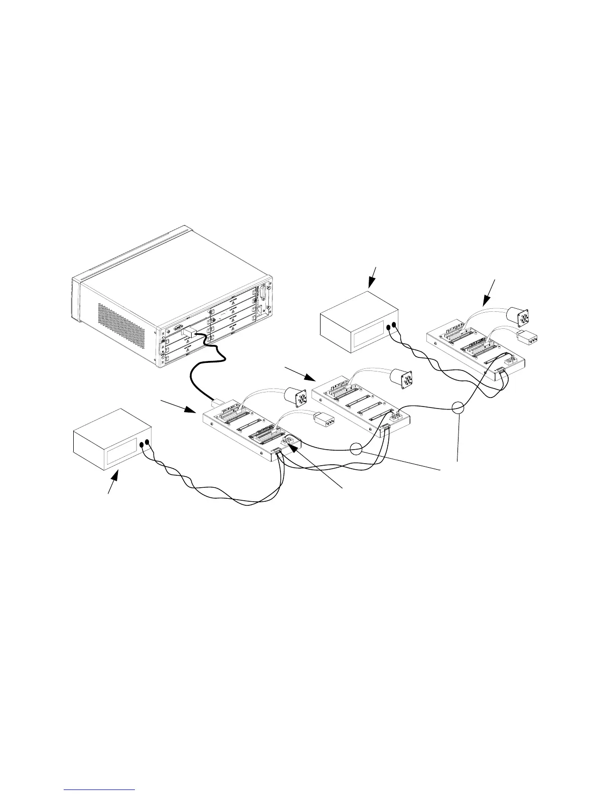
An alternate system configuration, using multiple remote modules,
is illustrated below. As shown, the driver interface module is installed in
slot 1. The first remote module, connected via the D- Sub cable, is the
master remote module. Additional remote modules are connected in a
daisy chain fashion using standard ethernet RJ- 45 connectors and Cat 5
cable. These remote modules are referred to as slaves. The master and
first slave remote module are powered from a 24 Volt external power
supply. The last slave remote module is powered from a 12 Volt external
power supply.
• All slave modules must obtain power from an external power supply.
the master remote module may obtain power from the mainframe.
• The Cat 5 Ethernet connecting cable must be plugged-in to port 1 on
the master remote module. Port 1 and Port 2 are interchangeable on
all slaves.
• Each remote module may be powered by a separate power supply.
All distribution boards on each remote module must use the same
power supply voltage.
• You may have up to eight 34945EXTs in a system.
24 Volts
12 Volts
Remote Module 1
24 V Power Supply
12 V Power Supply
Remote Module 2
Remote Module(s)
3 through 8
Master
Slave
Slave(s)
Must connect to Port 1
on master remote module
RJ-45 Connectors
and Cables
 Loading...


