274 34980A User’s Guide
10 64-Bit Digital I/O Module with Memory and Counter
Synchronous Buffered Inputs You can use synchronous mode handshake
with buffered (memory) input operations. (Buffered operations are
described in more detail beginning on page 277.) For buffered input
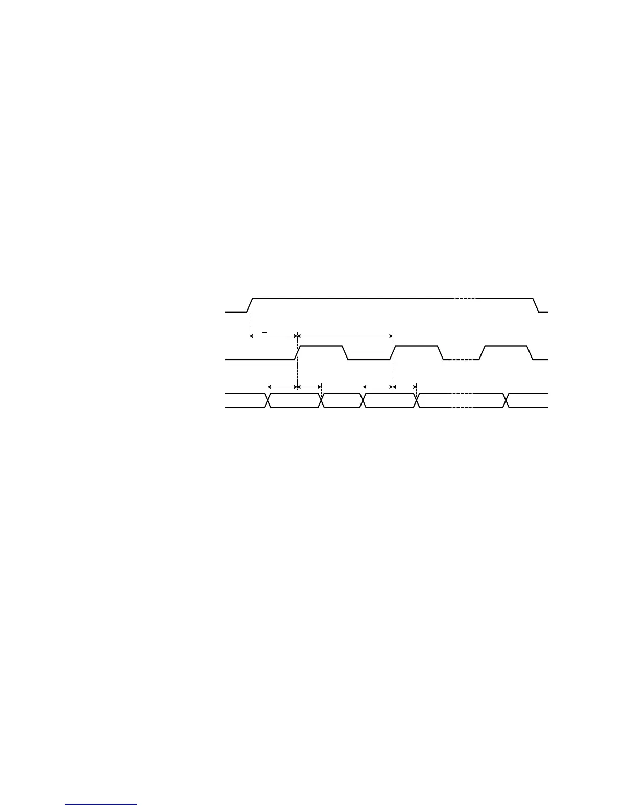
operations, the H0 line acts as a start/stop line. This line will be set high
when the memory input command is executed and will return low when
the memory input operation has completed. The H1 line is not used and is
set to high impedance.
An external strobe input on the H2 line controls the pace of memory
transfers. The sending device must ensure the data is valid before the
T
SETUP
and stays valid until after T
HOLD
. T
SETUP
is 30 ns and T
HOLD
is
55 ns.
A synchronous buffered input using an external clock is shown in the
diagram below (default handshake line polarity).
For example, the following SCPI commands set a 34950A in slot 5 to have
an 8- bit input using synchronous handshake with an external strobe input.
The number of bytes to read into memory is set to infinite (continuous
reading into memory until the memory is stopped). The memory is
enabled and then triggered. The start/stop line is set high following the
first byte handshake and remains high until the last byte is captured.
CONF:DIG:WIDT BYTE, (@5101)
CONF:DIG:DIR INP, (@5101)
CONF:DIG:HAND SYNC, (@5101)
SENS:DIG:MEM:SAMP:COUN 0, (@5101)
SENS:DIG:MEM:ENAB ON, (@5101)
SENS:DIG:MEM:STAR (@5101)
H0 (Start/
Stop)
H2 (Strobe In)
Data In
Valid Don't-Care
T
SETUP
T
HOLD
T
CYCLE
>
100 ns
T
SETUP
T
HOLD
Valid
(Last Cycle)
Don't-Care Don't-Care Don't-CareValid
> 50 ns
 Loading...


