Installation
Step 8. Attaching tubing to detector manifolds
36
6890 with Manual Pressure Control
1. Turn off the gas supplies to be connected at their sources.
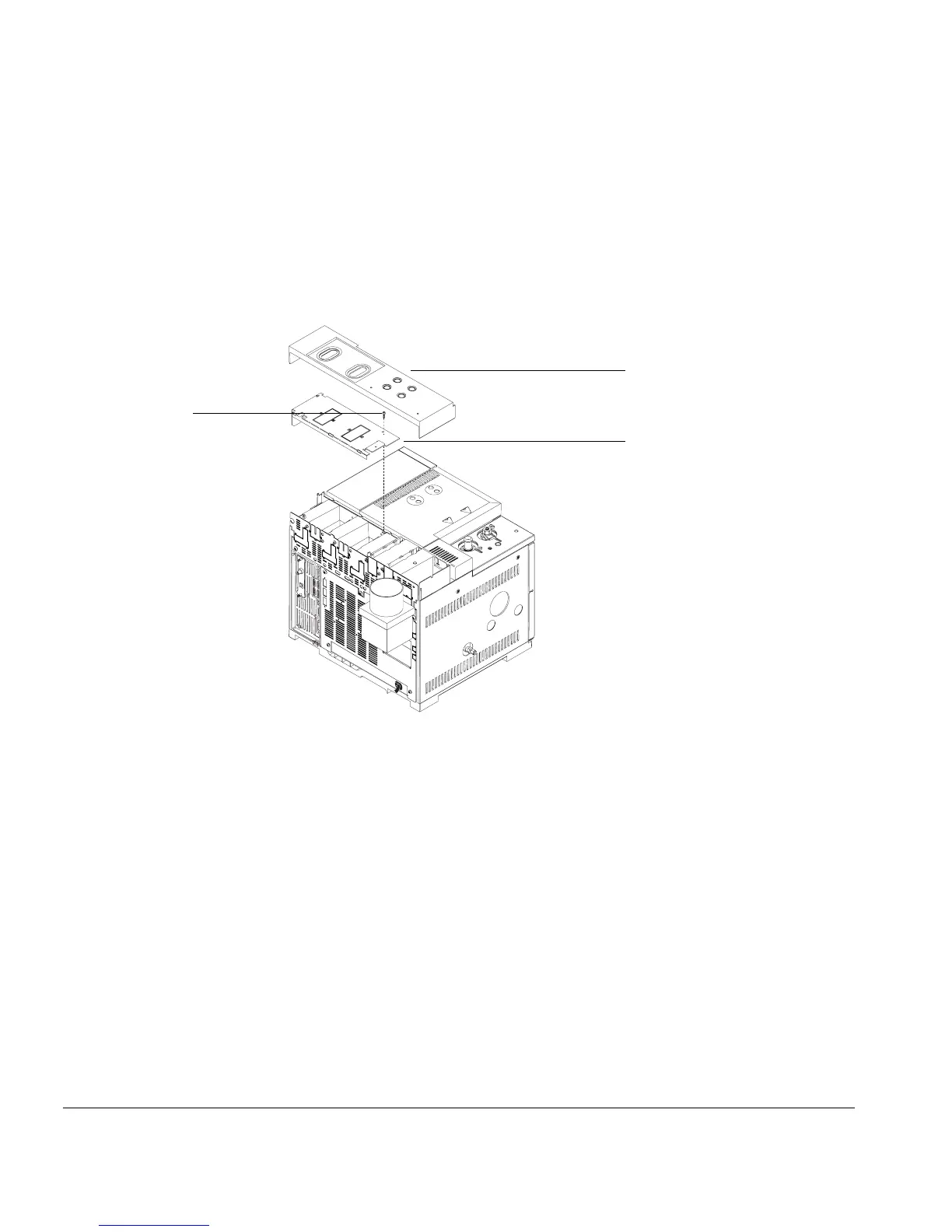
2. Remove the top rear cover by lifting it up. Remove the screw securing the
RFI cover and remove the RFI cover. See Figure 15.
Figure 15. Removing covers
3. A slot on the back of the GC, just left of the back inlet manifold, can be used
to bend copper tubing to the right angle for connection. Insert the tubing
until you feel resistance and bend it upward.
4. The FID uses hydrogen, air, and a makeup gas. The inlets are labeled; connect
the tubing to the appropriate inlet with a
SWAGELOK nut. Connect the makeup
gas to the fitting on the regulator. The other gases are connected to the
labeled fittings on the manifold. See Figure 16.
Screw securing
RFI cover
Top rear
cover
RFI cover

 Loading...


