55
Installation
Cable diagrams
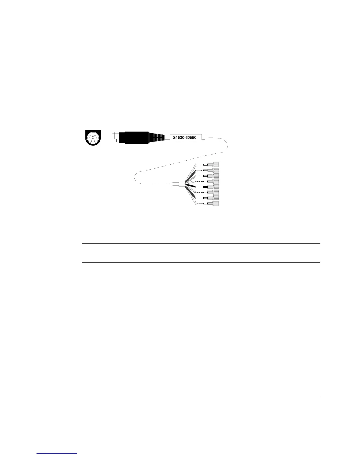
External event cable
Two passive relay contact closures and two 24-volt control outputs are available
for controlling external devices. Devices connected to the passive contact
closures must be connected to their own power source. See Figure 27 and
Table 13.
Figure 27. External event cable (part no. G1530-60590)
Table 13. External Event Connections
Connector Signal name Maximum rating Wire
terminations
Corresponds
to valve #
24 volt control output
1 24 volt output 1 75 mA output Yellow 5
2 24 volt output 2 75 mA output Black 6
3 Ground Red
4 Ground White
Relay contact closures (normally open)
5 Contact closure 1 48V AC/DC, 250 mA Orange 7
6 Contact closure 1 Green 7
7 Contact closure 2 48 V AC/DC, 250 mA Brown or
violet
8
8 Contact closure 2 Blue 8
1
2
3
4
5
678
6890 Gas Chromatograph
Connector
Wire terminations

 Loading...


