Installation
Cable diagrams
52
Cable diagrams
If you connect the GC to a non-Agilent instrument or to the 35900 A-to-D
Converter, you must know the function of each wire in the cable. See Table 10.
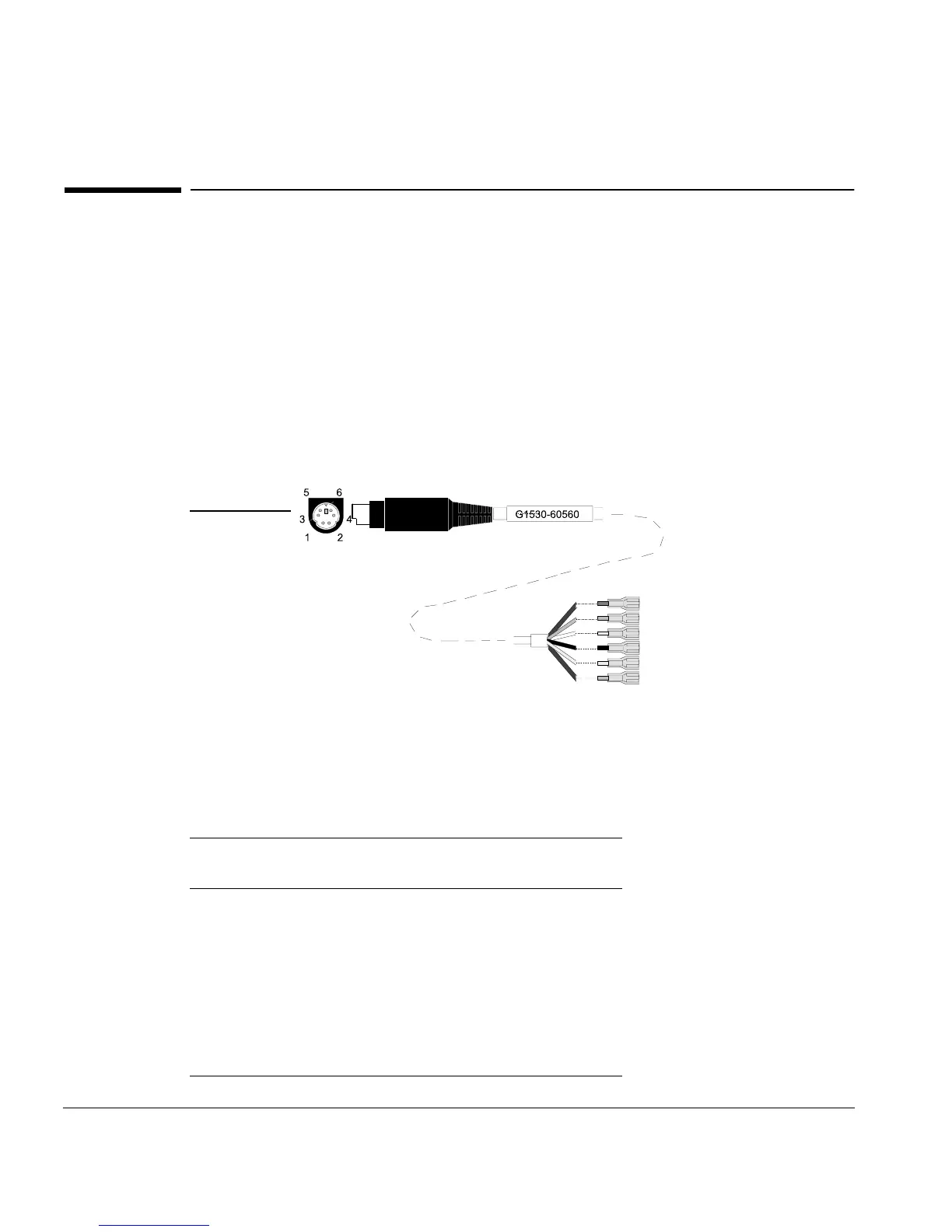
Analog cable, general use
The GC uses the general use analog cable to communicate with a
non-Agilent integrator. The general use cable is also used with non-Agilent
detectors. See Figure 24.
Figure 24. Analog cable, general use (part no. G1530-60560)
Table 10. Analog Cable, General Use Output Connections
Connector 1 Connector 2—Quick
connects
Signal
1 Brown or violet 0 to 1 mV (–)
2 White 0 to 1 V, 0 to 10 V(–)
3 Red 0 to 1 mV (+)
4 Black 1 V (+)
6 Blue 10 V (+)
Shell Orange Ground
Shell
Connector 1
Connector 2

 Loading...


