39
Installation
Step 10. Attaching cryogenic liquid supplies
Step 10. Attaching cryogenic liquid supplies
Cryogenic cooling allows you to operate the GC below ambient temperature. A
solenoid valve introduces liquid coolant, either CO
2
or N
2
, at a rate appropriate
to cool the oven to the desired temperature.
The choice of coolant depends largely on how frequently you use cryogenic
cooling. You cannot use CO
2
and N
2
interchangeably because they require
different valve assemblies. For more information on choosing cryogenic coolant,
see “Cryogenic cooling requirements” on page 18.
Flared or AN tubing fittings are commonly used to connect the liquid supply
tubing to the cryo coolant tank. Check with the supplier of the coolant before
plumbing to be sure you have the correct fittings.
Attaching liquid carbon dioxide
WARNING Do not use copper or thin-wall stainless steel tubing! Either presents an
explosion hazard.
Caution Do not use padded tanks for CO
2
supplies. The cryogenic valve is not designed
to handle the higher pressures padded tanks generate.
Materials needed:
❐ 1/8-inch heavy-wall, stainless steel tubing
❐ Tubing cutter
❐ 1/8-inch
SWAGELOK nuts and ferrules
❐ Two 7/16-inch wrenches
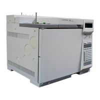
1. Locate the inlet for liquid CO
2
on the left side of the GC. Prepare enough
tubing to reach from the supply tank to this fitting. See Figure 17.
 Loading...
