45
Installation
Step 13. Connecting cables
Step 13. Connecting cables
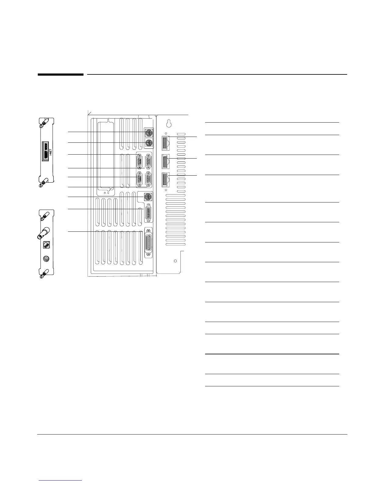
Figure 20. Overview of cable connections on the back of the GC
Number Description
1 Signal 1 — Analog output for
integrators or A/D converters
2 Signal 2 — Analog output for
integrators or A/D converters
3 and 5 Remote start-stop for synchronizing
the GC, integrators, automatic
samplers, Agilent MSD, and other GCs
4 Modem — RS-232 for modem,
computer, or controller devices
6 Sampler — Control for 7673 Automatic
Liquid Sampler*
7 External event contact closures and
24-volt outputs for valve control
8 BCD input for stream selection valves,
headspace sampler, or other device
9 GPIB for Agilent ChemStation
and/or MSD
10a Optional MIO INET card for
3396B/C or 3397 integrators
10b Optional MIO LAN card
11 Sampler G2613A Automatic Liquid
Sampler, default front injector
12 Sampler G2613A Automatic Liquid
Sampler, default back injector
13 Sampler G2614A tray
* Not used if the GC has an internal controller for the
7683 ALS
1
2
3
4
5
6
7
8
9
11
12
13
10a
or
10b

 Loading...


