CW Frequency
Switching Time
(Across Bandswitch
Points)
2.
On
the
oscilloscop
e,
set:
Channel
1:
Display On
Preset
TTL
Input
Coupling
dc
Input Impedance
1M
Channel
2:
Display Off
Timebase:
Time/Division 10
ms
Delay
Reference
At
left
Delay
0
10
ms
Sweep
Triggered
Trigger:
Trigger
Mode
Edge
Trigger
Src
Chan
1
Trigger
Level
1.6
V
Trigger
Slope
Pos
Display:
Display
Mode
Repetitive
Averaging
Off
3.
On
the
syn
thesizer,
set
the
rst
Initial
CW F
r
e
quency
in
T
able
2-7
.
4.
On
the
oscilloscop
e,
clear
the
displa
y
.
The
oscilloscop
e
should
displa
y
Awaiting Trigger
.
5. On
the
syn
thesizer,
set
the
rst
Se
c
ond
CW
F
r
e
quency
in
T
able
2-7
.
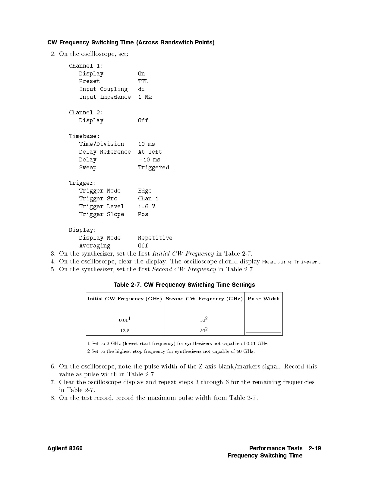
T
able
2-7.
CW
Frequency
Switching
Time
Settings
Initial CW
Frequency
(GHz)
Second CW
Frequency
(GHz)
Pulse Width
0.01
1
50
2
13.5 50
2
1
Set to 2 GHz (low
est start frequency) for
synthesizers not capable of 0.01 GHz.
2
Set to the highest stop frequency for synthesizers not capable of 50 GHz.
6. On the oscilloscop e, note the pulse width of the Z-axis blank/markers signal. Record this
value as pulse width in T
able 2-7.
7.
Clear the oscilloscop e displa
y and repeat steps 3 through 6 for the remaining frequencies
in Table 2-7.
8. On the test record, record the maximum pulse width from Table 2-7.
Agilent 8360 Performance Tests
Frequency Switching Time
2-19
 Loading...


