5.
Po
wer
Flatness
Description
and Procedure
This pro
cedure uses
the user
atness correction
array
to
automatically
measure
p
o
w
er
atness.
The
p
o
w
er
meter
is
connected
directly
to
the
syn
thesizer's
RF
output.
The
synthesizer
con
trols
the
po
wer
meter via
GPIB while
the
p
o
w
er
meter
measures
the
RF
output.
(There
cannot b
e
another
con
troller
on
the
GPIB
during
this
test.)
If
the
syn
thesizer
has
a
step
atten
uator,
it
is
set
to
0
dB
so
that
any
input in
to the
atness arra
y
indicates
the
RF
output
p
ow
er atness.
Note
This p
erformance test
requires
an
HP/Agilen
t
437B
p
o
w
er
meter.
The
correct
p
o
w
er
sensor
calibration
factors
m
ust
b
e
loaded
and
selected.
This
pro
cedure
deletes
an
y
existing
user
atness
correction
arra
y
.
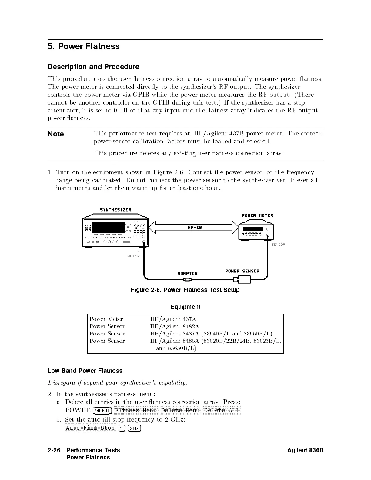
1.
T
urn
on
the
equipmen
t
sho
wn
in
Figure
2-6
.
Connect
the
p
o
w
er
sensor
for
the
frequency
range
b
eing
calibrated.
Do
not
connect
the p
ow
er sensor
to
the
syn
thesizer
y
et.
Preset
all
instrumen
ts
and
let
them
w
arm
up
for
at
least
one
hour.
Figure
2-6.
P
o
w
er
Flatness
T
est
Setup
Equipment
P
ow
er Meter
HP/Agilent
437A
P
ow
er
Sensor
HP/Agilen
t
8482A
P
ower Sensor HP/Agilent 8487A (83640B/L and 83650B/L)
P
ower Sensor HP/Agilent 8485A (83620B/22B/24B, 83623B/L,
and 83630B/L)
Low Band P
ower Flatness
Disregardifb
eyond your synthesizer's c
apability.
2. In the synthesizer's atness menu:
a. Delete all entries in the user atness correction array. Press:
POWER
4
MENU
5
NNNNNNNNNNNNNNNNNNNNNNNNNNNNNNNNNNNNNN
Fltness Menu
NNNNNNNNNNNNNNNNNNNNNNNNNNNNNNNNNNN
Delete Menu
NNNNNNNNNNNNNNNNNNNNNNNNNNNNNNNN
Delete All
b. Set the auto ll stop frequency to 2 GHz:
NNNNNNNNNNNNNNNNNNNNNNNNNNNNNNNNNNNNNNNNNNNN
Auto Fill Stop
4
2
54
GHz
5
2-26 Performance Tests
Power Flatness
Agilent 8360
 Loading...


