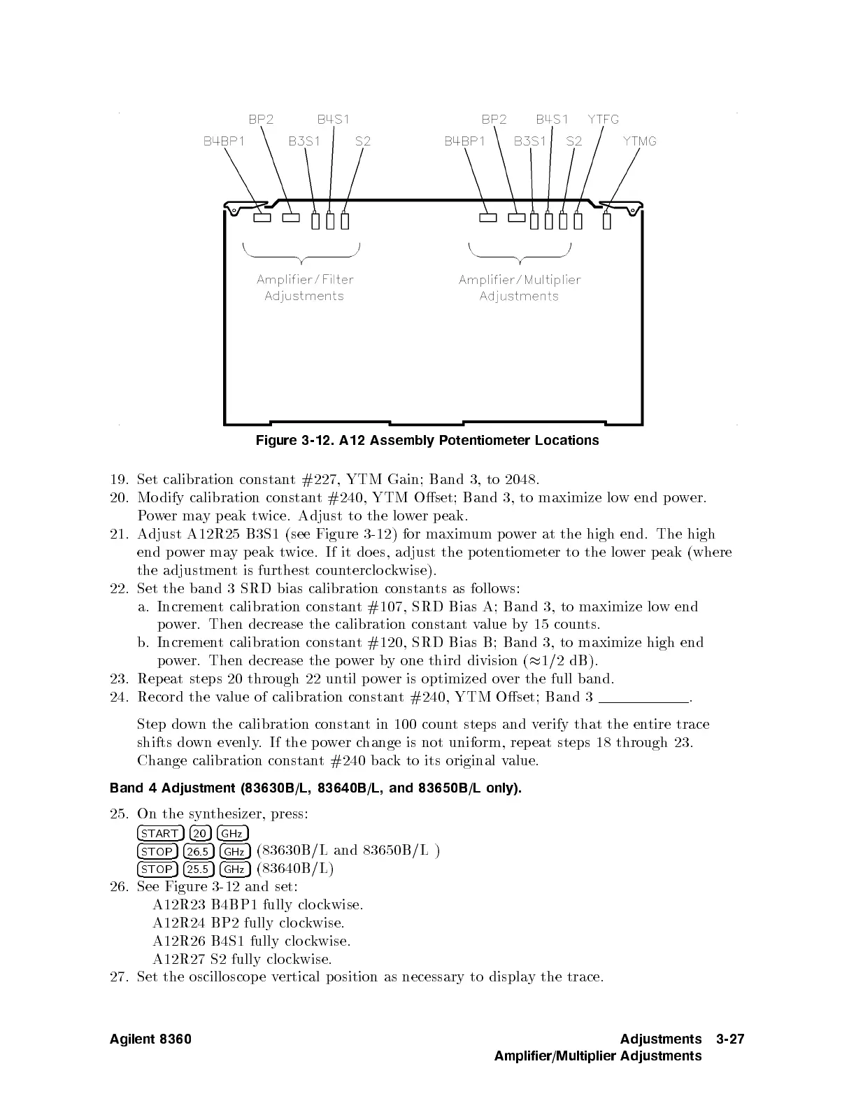
Figure
3-12. A12
Assembly P
otentiometer Locations
19.
Set
calibration
constan
t #227,
YTM Gain;
Band
3,
to
2048.
20.
Mo
dify
calibration
constan
t
#240,
YTM
Oset;
Band
3,
to maximize
low
end
p
o
w
er.
P
o
w
er
ma
y
p
eak
t
wice.
Adjust
to
the
lo
w
er
p
eak.
21.
Adjust
A12R25 B3S1
(see
Figure
3-12
)
for
maxim
um
p
o
w
er
at
the
high
end.
The
high
end
p
o
w
er
ma
y
p
eak
t
wice. If
it
do
es,
adjust
the
p
oten
tiometer
to
the
lo
w
er
p
eak
(where
the
adjustmen
t
is
furthest
coun
terclo
c
kwise).
22. Set
the
band
3
SRD
bias
calibration
constan
ts
as
follo
ws:
a.
Incremen
t
calibration
constan
t
#107,
SRD Bias
A; Band
3,
to
maximize
lo
w
end
p
o
w
er.
Then
decrease
the
calibration
constan
t
v
alue
b
y
15 coun
ts.
b. Incremen
t
calibration
constan
t
#120,
SRD
Bias
B;
Band
3,
to
maximize
high
end
p
ow
er. Then
decrease the
po
w
er
b
y
one
third
division
(
1/2
dB).
23.
Rep
eat
steps
20
through
22
un
til
p
ow
er is
optimized o
v
er
the
full
band.
24.
Record
the
v
alue
of
calibration
constan
t
#240,
YTM
Oset;
Band
3
.
Step
do
wn
the
calibration
constan
t
in
100
coun
t
steps
and
v
erify
that the
entire
trace
shifts
down
evenly
.If
the p
o
w
er
c
hange
is
not
uniform,
rep
eat
steps
18 through
23.
Change calibration
constant #240 bac
k to its original v
alue.
Band 4 Adjustment (83630B/L, 83640B/L, and 83650B/L only).
25. On the syn
thesizer, press:
4
START
54
20
54
GHz
5
4
STOP
54
26.5
54
GHz
5
(83630B
/L and 83650B/L )
4
STOP
54
25.5
54
GHz
5
(83640B
/L)
26. See Figure 3-12 and set:
A12R23 B4BP1 fully clo ckwise.
A12R24 BP2 fully clo ckwise.
A12R26 B4S1 fully clo ckwise.
A12R27 S2 fully clo ckwise.
27. Set the oscilloscop e vertical position as necessary to display the trace.
Agilent 8360 Adjustments
Amplifier/Multiplier Adjustments
3-27
 Loading...


