9.
Spurious Signals
(Non-Harmonic)
Description
and Procedure
Use this
pro cedure
to measure
known,
xed, oset
spurs
that
are
generated
in
the
frequency
syn
thesis
section
of
the
syn
thesizer.
The
syn
thesizer
is
set
to
v
arious
CW
frequencies where
these
spurious
signals
will most
likely
o ccur.
Then the
sp
ectrum
analyzer
is
tuned
to
the
spur
frequencies to
measure
their
lev
els.
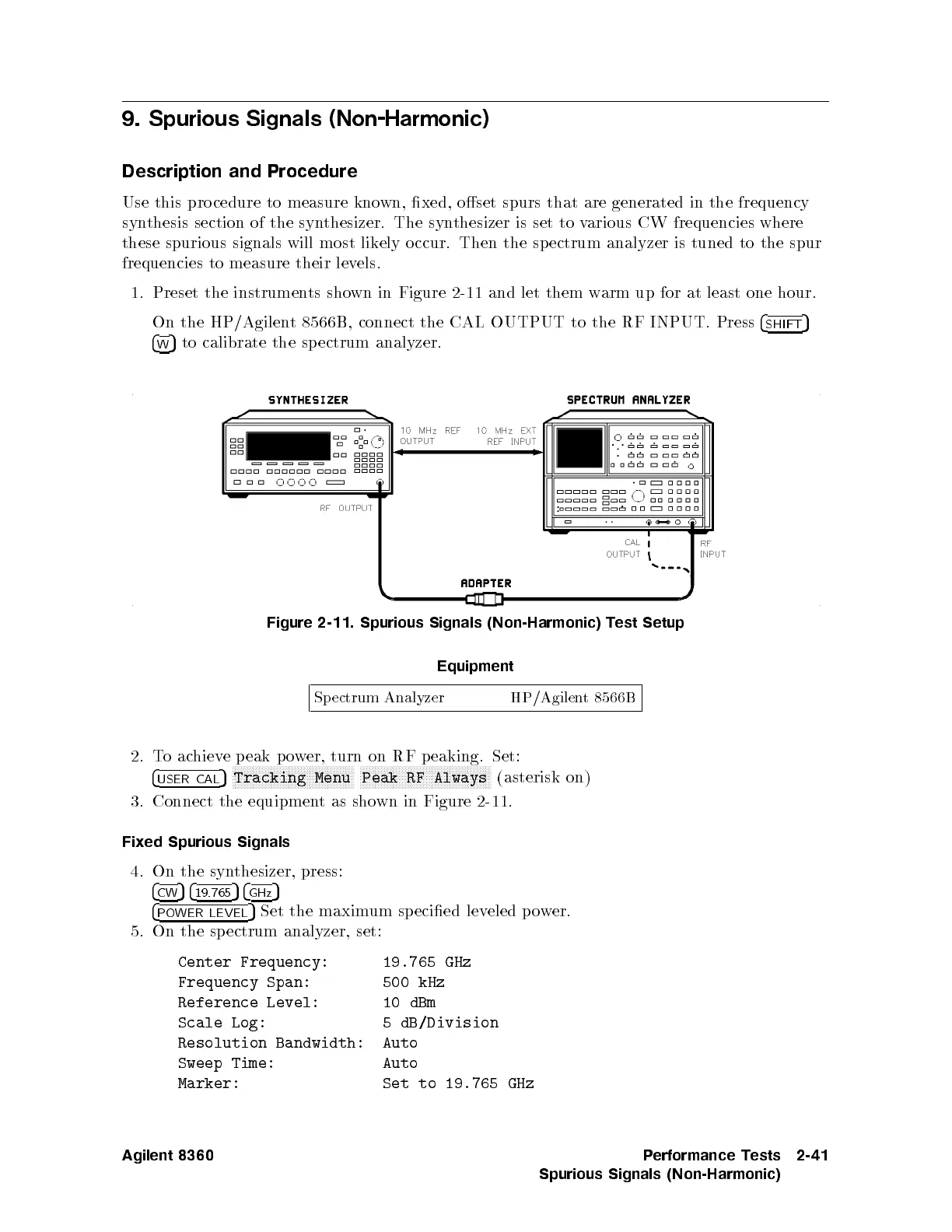
1.
Preset
the
instrumen
ts
sho
wn
in
Figure
2-11
and let
them w
arm up
for at
least
one
hour.
On
the
HP/Agilen
t
8566B,
connect
the
CAL
OUTPUT
to the
RF INPUT.
Press
4
SHIFT
5
4
W
5
to
calibrate the
spectrum
analyzer.
Figure
2-11.
Spurious
Signals
(Non-Harmonic)
T
est
Setup
Equipment
Sp
ectrum
Analyzer
HP/Agilent
8566B
2.
T
o
ac
hiev
e
p
eak
p
ow
er, turn
on RF
p
eaking.
Set:
4
USER CAL
5
N
N
NN
NN
NN
N
N
N
N
N
N
N
N
N
N
N
N
N
N
N
N
N
N
N
NN
NN
NN
N
N
N
N
N
N
N
N
Tracking
Menu
N
N
NN
NN
NN
N
N
N
N
N
N
N
N
N
N
N
N
N
N
N
N
N
N
N
NN
NN
NN
N
N
N
N
N
N
N
N
N
N
N
Peak
RF
Always
(asterisk
on)
3.
Connect
the
equipmen
t
as
sho
wn
in
Figure
2-11.
Fixed
Spurious
Signals
4. On the syn
thesizer, press:
4
CW
54
19.765
54
GHz
5
4
POWER LEVEL
5
Set the maximum specied lev
eled po
wer.
5. On the spectrum analyzer, set:
Center Frequency:
19.765 GHz
Frequency Span: 500 kHz
Reference Level: 10 dBm
Scale Log: 5 dB/Division
Resolution Bandwidth: Auto
Sweep Time: Auto
Marker: Set to 19.765 GHz
Agilent 8360 Performance Tests
Spurious Signals (Non-Harmonic)
2-41
 Loading...


