8.On
the oscilloscop
e:
a.
Adjust the
timebase dela
y
to
p
osition
the
rising
edge
of
the
pulsed
RF
near the
center
of
the
displa
y
.
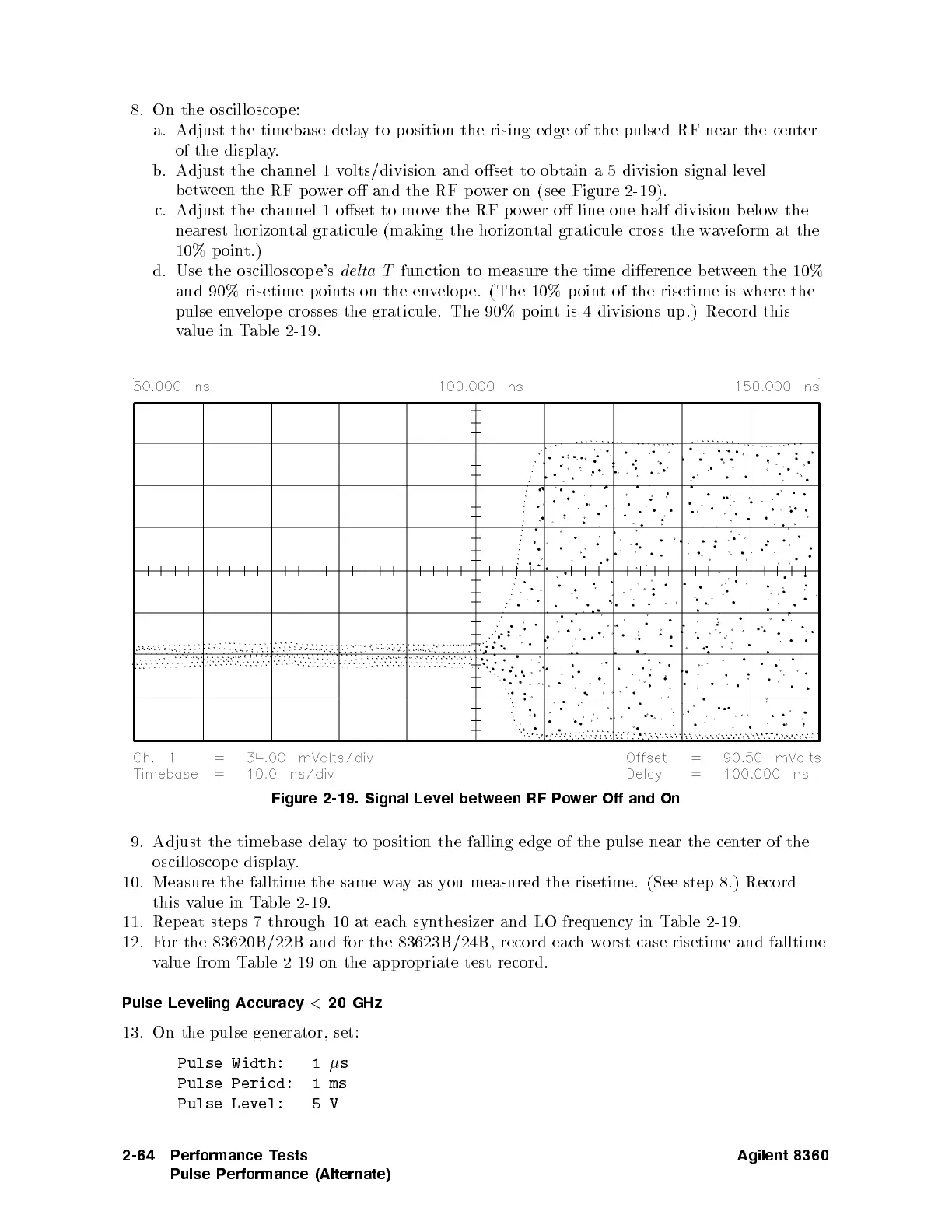
b. Adjust
the c
hannel 1
volts/division
and oset
to obtain
a
5
division
signal
lev
el
b
etw
een
the
RF
p
o
w
er
o
and
the
RF
po
wer
on (see
Figure 2-19
).
c.
Adjust
the
c
hannel
1oset
to mo
ve
the RF
po
wer
o line
one-half
division
b
elo
w
the
nearest horizon
tal graticule
(making the
horizontal
graticule
cross
the
w
a
v
eform
at
the
10%
p
oin
t.)
d.
Use
the
oscilloscop
e's
delta
T
function to
measure the
time dierence
bet
w
een
the
10%
and 90%
risetime p
oints
on
the
en
v
elop
e.
(The
10%
p
oin
t
of
the
risetime
is
where
the
pulse
en
v
elop
e
crosses
the
graticule.
The
90%
p
oin
t
is
4 divisions
up.) Record
this
v
alue in
Table
2-19.
Figure
2-19.
Signal
Lev
el
betw
een
RF
P
o
w
er
Off
and On
9.
Adjust
the
timebase
dela
y
to
p
osition
the falling
edge
of
the
pulse
near
the
cen
ter
of
the
oscilloscop e displa
y.
10. Measure the falltime the same w
ayas y
ou measured the risetime. (See step 8.) Record
this v
alue in T
able 2-19
.
11. Repeat steps 7 through 10 at eac
h
synthesizer and LO frequency in T
able 2-19.
12. F
or the 83620B/22B and for the 83623B/24B, record eac
hw
orst case risetime and falltime
value from T
able 2-19 on the appropriate test record.
Pulse Leveling Accuracy
<
20 GHz
13. On the pulse generator, set:
Pulse Width: 1
s
Pulse Period: 1ms
Pulse Level: 5V
2-64 Performance Tests
Pulse Performance (Alternate)
Agilent 8360
 Loading...


