EasyManuals Logo
Home>Agilent Technologies>Portable Generator>83640B

Agilent Technologies 83640B Service Guide

Agilent Technologies 83640B
603 pages
To Next Page IconTo Next Page
To Previous Page IconTo Previous Page
Page #496 background imageLoading...
Page #496 background image
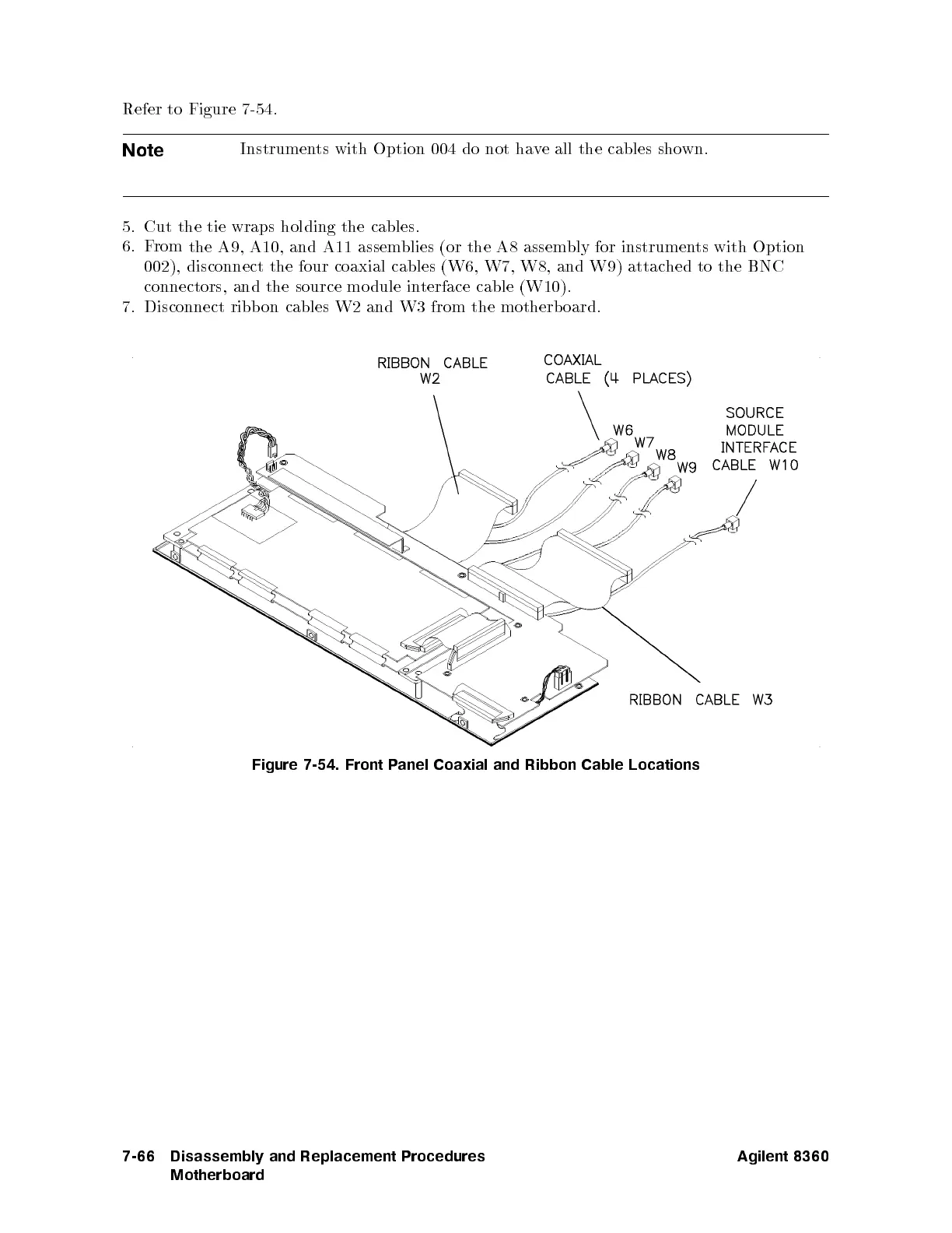
Refer to
Figure 7-54
.
Note
Instrumen
ts with
Option 004
do
not
ha
v
e
all
the
cables
sho
wn.
5.
Cut
the tie
wraps holding
the cables.
6.
F
rom
the
A9,
A10,
and
A11
assem
blies
(or
the
A8
assem
bly
for
instrumen
ts
with Option
002),
disconnect
the
four
coaxial
cables
(W6,
W7,
W8,
and W9)
attached
to the
BNC
connectors, and
the source
mo dule
interface
cable
(W10).
7.
Disconnect
ribb
on
cables
W2
and
W3
from
the
motherb
oard.
Figure
7-54.
Front P
anel Coaxial
and Ribbon
Cable
Locations
7-66 Disassembly and Replacement Procedures
Motherboard
Agilent 8360

Table of Contents

Other manuals for Agilent Technologies 83640B

Questions and Answers:

Question and Answer IconNeed help?

Do you have a question about the Agilent Technologies 83640B and is the answer not in the manual?

Agilent Technologies 83640B Specifications

General IconGeneral
BrandAgilent Technologies
Model83640B
CategoryPortable Generator
LanguageEnglish

Related product manuals