EasyManua.ls Logo

Agilent Technologies 83640B

Agilent Technologies 83640B
603 pages
To Next Page IconTo Next Page
To Previous Page IconTo Previous Page
Loading...
3.
Rear P
anel BNC
Connectors
Remo
v
al
and
Aux
Output
Disconnection
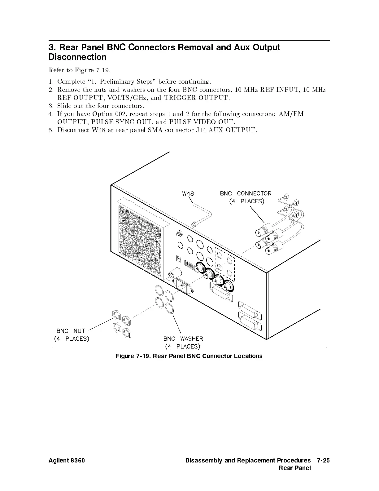
Refer
to
Figure
7-19
.
1.
Complete \1.
Preliminary Steps"
before
contin
uing.
2.
Remo
v
e
the
n
uts
and
w
ashers
on
the
four
BNC
connectors,
10 MHz
REF INPUT,
10 MHz
REF
OUTPUT,
V
OL
TS/GHz,
and
TRIGGER OUTPUT.
3.
Slide out
the four
connectors.
4.
If
y
ou
ha
v
e
Option
002,
rep
eat
steps
1
and 2
for the
following
connectors: AM/FM
OUTPUT,
PULSE
SYNC
OUT,
and PULSE
VIDEO OUT.
5.
Disconnect W48
at
rear
panel
SMA
connector
J14
A
UX
OUTPUT.
Figure 7-19.
Rear P
anel BNC Connector Locations
Agilent 8360 Disassembly and Replacement Procedures
Rear Panel
7-25

Table of Contents

Other manuals for Agilent Technologies 83640B

Related product manuals