Harmonic Measurement
<
20
GHz
3.
Connect
the
equipmen
t
as
sho
wn
in Figure
2-9.
4.
On the
synthesizer,
press:
4
POWER
LEVEL
5
Set
the maxim
um
sp
ecied
lev
eled
p
o
w
er.
SWEEP
4
MENU
5
NN
NN
NN
NN
N
N
N
N
N
N
N
N
N
N
N
NN
NN
NN
NN
NN
NN
NN
N
N
N
N
N
Manual Sweep
5. On
the sp
ectrum analyzer,
set
the
rst
set
of
start
and
stop
frequencies
from
T
able
2-9
.
Then
set:
Reference
Level:
0
20
dBm
Scale
Log:
5
dB/Division
Bandwidth
Resolution: 3
MHz
Video
Bandwidth
3
MHz
T
able
2-9.
Start
and
Stop
Frequencies
Start
F
requency
(GHz)
Stop
F
requency
(GHz)
0.01
1
2.0
2.0 7.0
7.0 13.5
13.5 20.0
1
Set
to
2
GHz
for
83622B
/24B.
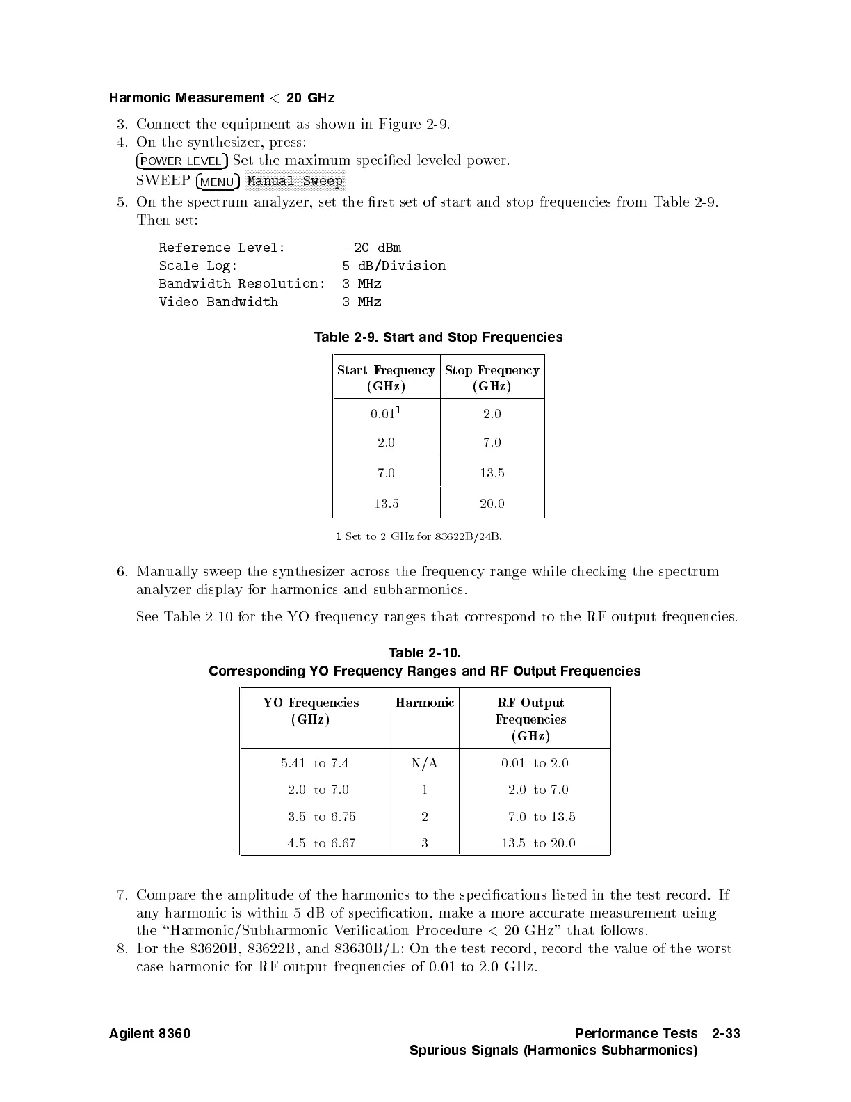
6.
Man
ually
sw
eep
the
syn
thesizer
across
the
frequency
range
while
c
hec
king
the
sp
ectrum
analyzer
displa
y
for
harmonics and
subharmonics.
See
T
able 2-10
for the
YO
frequency
ranges
that
corresp
ond
to
the
RF
output
frequencies.
T
able
2-10.
Corresponding YO
Frequency Ranges
and
RF
Output
Frequencies
YO
F
requencies
(GHz)
Harmonic RF
Output
F
requencies
(GHz)
5.41 to 7.4 N/A 0.01 to 2.0
2.0 to 7.0 1 2.0 to 7.0
3.5 to 6.75 2 7.0 to 13.5
4.5 to 6.67 3 13.5 to 20.0
7. Compare the amplitude of the harmonics to the specications listed in the test record. If
any harmonic is within 5 dB of sp ecication, make a more accurate measurement using
the \Harmonic/Subharmonic Verication Pro cedure
<
20 GHz" that follows.
8.For the 83620B, 83622B, and 83630B/L: On the test record, record the value of the worst
case harmonic for RF output frequencies of 0.01 to 2.0 GHz.
Agilent 8360 Performance Tests
Spurious Signals (Harmonics Subharmonics)
2-33
 Loading...


