EasyManuals Logo
Home>Agilent Technologies>Portable Generator>83640B

Agilent Technologies 83640B Service Guide

Agilent Technologies 83640B
603 pages
To Next Page IconTo Next Page
To Previous Page IconTo Previous Page
Page #497 background imageLoading...
Page #497 background image
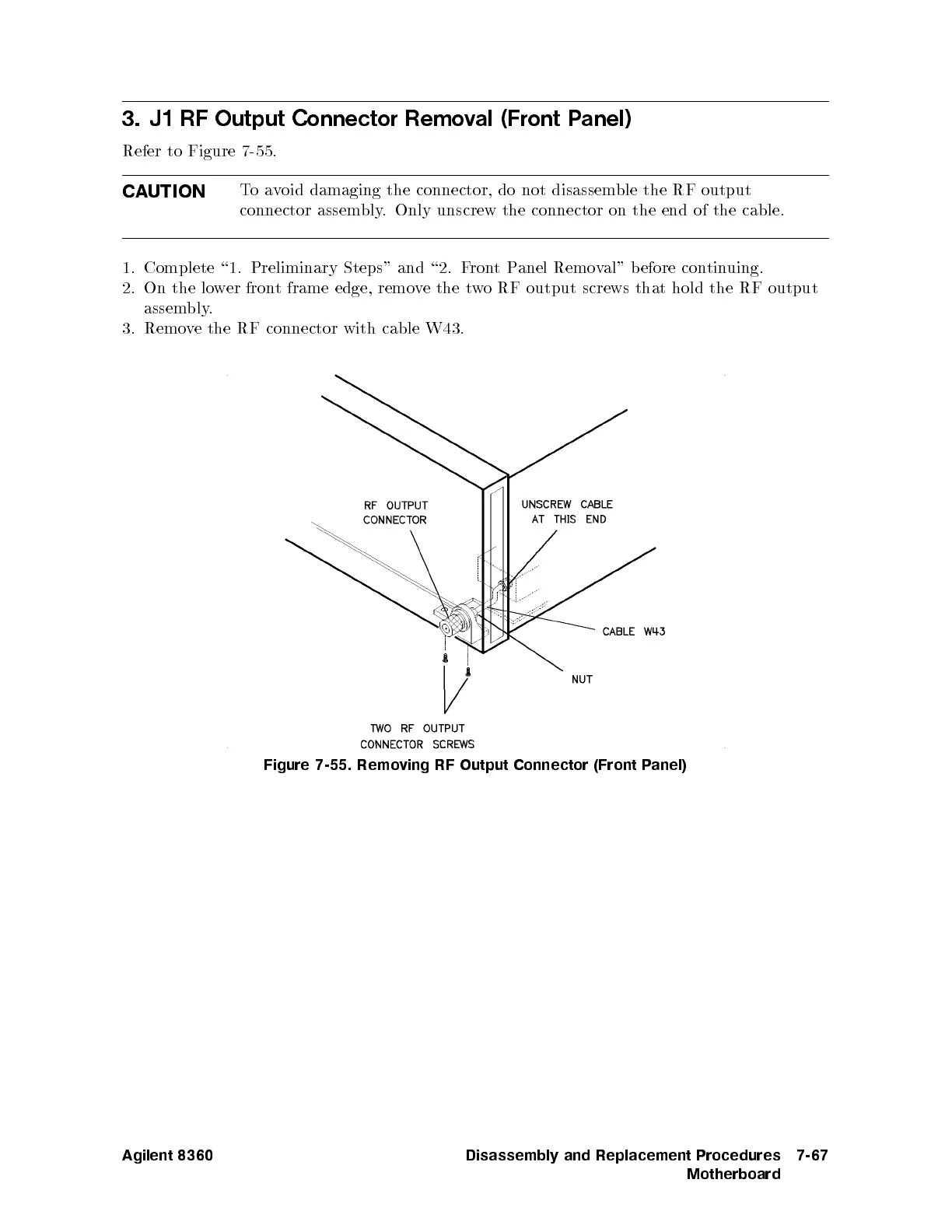
3.
J1 RF
Output Connector
Remo
v
al
(Front
P
anel)
Refer to
Figure 7-55
.
CA
UTION
T
o
a
v
oid
damaging
the
connector,
do
not
disassemble
the RF
output
connector
assembly
. Only
unscrew the
connector on
the end
of the
cable.
1. Complete
\1. Preliminary
Steps" and
\2. F
ron
t
P
anel
Remo
v
al"
b
efore
con
tin
uing.
2.
On
the
lo
w
er
fron
t
frame
edge,
remo
v
e
the
t
w
oRF
output screws
that hold
the RF
output
assem
bly
.
3. Remo
ve
the RF
connector
with
cable
W43.
Figure
7-55. Remo
ving RF
Output Connector
(Front
P
anel)
Agilent 8360 Disassembly and Replacement Procedures
Motherboard
7-67

Table of Contents

Other manuals for Agilent Technologies 83640B

Questions and Answers:

Question and Answer IconNeed help?

Do you have a question about the Agilent Technologies 83640B and is the answer not in the manual?

Agilent Technologies 83640B Specifications

General IconGeneral
BrandAgilent Technologies
Model83640B
CategoryPortable Generator
LanguageEnglish

Related product manuals