For
the 83640B
/L and
83650B/L
only,
also
press:
4
SERVICE
5
NN
N
N
N
N
N
N
N
N
N
N
N
NN
NN
NN
NN
NN
NN
NN
N
N
N
N
N
Tools
Menu
NN
N
N
N
N
N
N
N
N
N
N
N
NN
NN
NN
NN
NN
NN
NN
N
N
N
N
N
N
N
N
N
N
N
NN
NN
NN
NN
N
Disable
Doubler
(asterisk
o
)
Connect
the p
o
w
er
meter
to
the
syn
thesizer
RF
OUTPUT
through
the p
ow
er sensor
and
10
dB
atten
uator
(see
Figure 3-18
). Adjust
the oscilloscop
e horizon
tal con
trol to
place
the lo
wp
ow
er p
oint
on
a
v
ertical
graticule
and
note
the
p
osition.
Select
man
ual
sw
eep.
Press
SWEEP
4
MENU
5
N
N
N
N
N
N
N
N
N
N
N
N
N
N
N
N
N
NN
NN
NN
NN
N
N
N
N
N
N
N
N
N
N
N
N
N
Manual
Sweep
(asterisk
on).
Use
the
arro
w
k
eys
to
adjust
the
CW
frequency
to
the
minim
um p
ow
er p
oint
on
the
oscilloscop
e.
On
the
p
o
w
er
meter,
c
hec
k that
the p
ow
er at
this
p
oin
t
is
not
less
than
the
sp
ecied
maximum
leveled
po
wer
(note
that
p
o
w
er
is
atten
uated
b
y
10
dB
).
If
it
is,
note the
level
and
frequency
,
and
c
hec
k
the
follo
wing:
a.
Compare
the
man
ually
adjusted
YTF
and
YTM
gain and
oset calibration
constants
(step 85)
to the
auto trac
k
ed
calibration
constan
ts.
A
large
dierence
in
v
alues
(sev
eral
h
undred
coun
ts)
indicates
a
p
ossible
misadjustmen
t.
The
auto
trac
king
values
are
correct.
b. If
the band
3
v
alues
are
within
500
coun
ts
of
the
limits
of
their
ranges,
rep
eat
the
B3S1,
B4S1,
and
B4BP1
adjustmen
ts
with
the
doubler
disabled.
c.
If
the
band 4
values
are within
500
coun
ts
of
the
limits
of
the
range,
rep
eat
the
B4S1
and
B4BP1
adjustmen
ts
with
the
doubler
disabled
(unless
y
ou ha
ve
just readjusted
these
adjustmen
ts
in
step
b).
d.
If the
problem con
tin
ues,
it
is
most
lik
ely
hardw
are-related.
Refer
to
the
A
gilent
T
e
chnolo
gies
8360
B-Series
Swept
Signal
Generator/
8360 L-Series
Swept
CW
Gener
ator
T
r
oublesho
oting
Guide
.
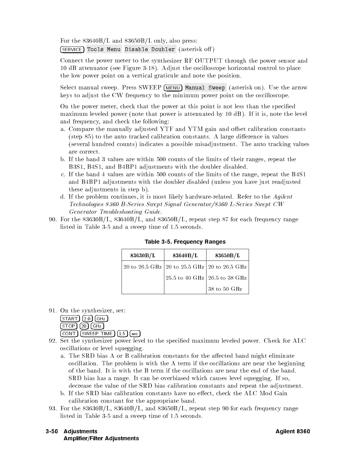
90.
F
or
the
83630B
/L,
83640B
/L,
and
83650B
/L,
rep
eat
step
87
for
eac
h
frequency
range
listed
in
T
able
3-5
and
a
sw
eep
time
of
1.5
seconds.
T
able
3-5.
Frequency
Ranges
83630B
/L
83640B
/L
83650B
/L
20
to
26.5
GHz
20
to
25.5
GHz
20
to
26.5
GHz
25.5
to
40
GHz
26.5
to
38
GHz
38
to
50
GHz
91.
On
the
syn
thesizer,
set:
4
START
54
2.0
54
GHz
5
4
STOP
54
20
54
GHz
5
4
CONT
54
SWEEP TIME
54
1.5
54
sec
5
92. Set the syn
thesizer po
wer lev
el to the specied maxim
um lev
eled
po
wer. Check for ALC
oscillations or lev
el squegging.
a. The SRD bias A or B calibration constan
ts for the aected band migh
t eliminate
oscillation. The problem is with the A term if the oscillations are near
the beginning
of the band. It is with the B term if the oscillations are near the end of the band.
SRD bias has a range. It can be overbiased which causes level squegging. If so,
decrease the value of the SRD bias calibration constants and rep eat the adjustment.
b. If the SRD bias calibration constants have no eect, check the ALC Mo d Gain
calibration constant for the appropriate band.
93. For the 83630B/L, 83640B/L, and 83650B/L, rep eat step 90 for each frequency range
listed in Table 3-5 and a sweep time of 1.5 seconds.
3-50 Adjustments
Amplifier/Filter Adjustments
Agilent 8360
 Loading...


