192 Chapter 2a
Making Adjustments: If 3335A Source Not Available
15a. Frequency Response of the 8590L, 8591C, and 8591E
Procedure for System Characterization
(75 Ω input)
1. Zero and calibrate the measuring receiver and 1 MHz to 1.8 GHz
power sensor as described in the measuring receiver operation
manual.
2. Zero and calibrate the power meter and the 75 Ω power sensor as
described in the power meter operation manual.
3. Press INSTRUMENT PRESET on the synthesized signal generator.
Set the synthesized signal generator controls as follows:
CW .................................................................. 41MHz
FREQ STEP ................................................... 37MHz
POWER LEVEL ............................................... 5dBm
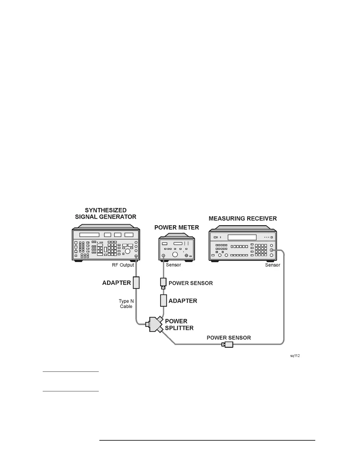
4. Connect the equipment as shown in Figure 2a-4.
Figure 2a-4 System Characterization Test Setup for 75 Ω inputs
CAUTION Use only 75 Ω cables, connectors, or adapters on instruments equipped
with 75 Ω inputs or damage to the input connectors will occur.
5. Adjust the synthesized signal generator POWER LEVEL for a
0 dBm reading on the measuring receiver.
 Loading...


