Chapter 2a 193
Making Adjustments: If 3335A Source Not Available
15a. Frequency Response of the 8590L, 8591C, and 8591E
6. Record the power meter reading in Column 4 of Table 2a-5, taking
into account the cal factors of both power sensors.
7. On the synthesized signal generator, press CW and STEP UP, to step
through the remaining frequencies listed in Table 2a-5.
At each new frequency repeat step 5 and step 6, and enter each
power sensor cal factor into the respective power meter.
Procedure
1. Zero and calibrate the measuring receiver and 1 MHz to 1.8 GHz
power sensor in log mode as described in the measuring receiver
operation manual.
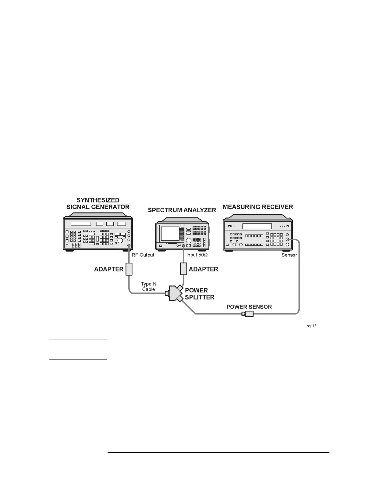
2. Connect the equipment as shown in Figure 2a-5.
Figure 2a-5 Frequency Response Setup
CAUTION Use only 75 Ω cables, connectors, or adapters on instruments equipped
with 75 Ω inputs or damage to the input connectors will occur.
3. Press INSTRUMENT PRESET on the synthesized signal generator.
Set the synthesized signal generator controls as follows:
CW ................................................................ 300MHz
FREQ STEP ................................................... 37MHz
POWER LEVEL ............................................. −9dBm
 Loading...


