Chapter 5 265
Troubleshooting the IF Section
IF Power-Level Measurement
To check linear gain control lines for the A14 log amplifier
Table 5-5 provides the control line voltages from the A7 analog interface
assembly to the A14 log amplifier assembly. When the analyzer is in
linear mode, the seven A14 log amplifier stages are biased to operate as
linear amplifiers. Four of the seven stages are also used to provide
40 dB of gain in 10 dB increments. The linear gains are enabled for the
reference levels indicated in Table 5-2 and Table 5-5. Two of the four
stages operate as one 20 dB amplifier and are controlled by the same
control line, IFG6.
Refer to “Troubleshooting the A15 Motherboard Assembly” in this
chapter when tracing control lines in the IF section.
When enabled, each control line has a −7.6 Vdc output. This voltage is
supplied by the −8 VT temperature-compensated power supply located
on the A14 assembly.
The entries in Table 5-5 are valid when the instrument is set up as
follows:
PRESET
SCALE LOG LIN, LIN
AMPTD UNITS, dBm
CAL
More 1 of 3
CORRECT ON OFF (OFF)
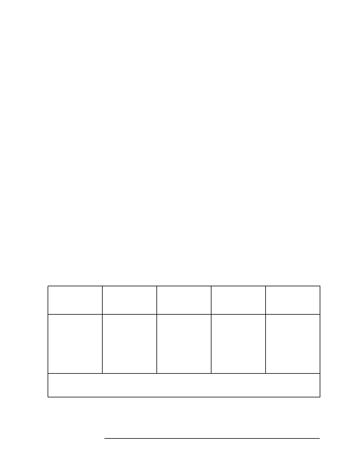
Table 5-5 Linear Gain Control Lines on the A14 Assembly
Reference
Level
(dBm)
A14 Gain in
Linear Mode
(dB)
IFG4
(10-1 dB Step)
A14P1-38
IFG5
(10-2 dB Step)
A14P1-39
IFG6
(20 dB Step)
A14P1-40
−500HHH
−60 10 L H H
−70 20 L L H
−80 30 L H L
−90 40 L L L
H = +14.3 Vdc (disabled)
L = −7.6 Vdc (enabled)

 Loading...
